EasyManuals Logo

HPE Apollo 2000 User Manual

HPE Apollo 2000
187 pages
To Next Page IconTo Next Page
To Previous Page IconTo Previous Page
Page #18 background imageLoading...
Page #18 background image
Component identification 18
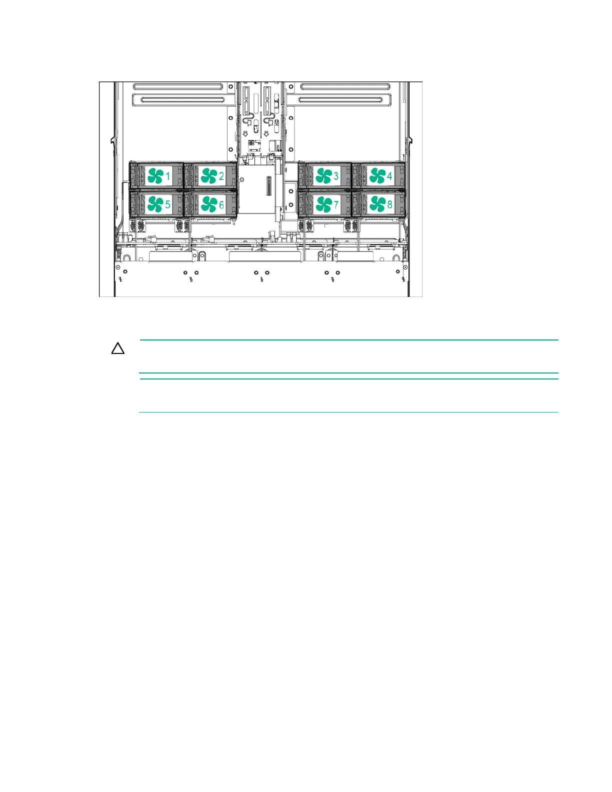
Fan locations
Drive bay numbering
CAUTION: To prevent improper cooling and thermal damage, do not operate the chassis
unless all bays are populated with a component or a blank.
NOTE: A SATA or mini-SAS cable must be installed in a node for the node to correspond to
drives in the chassis ("SATA and Mini-SAS cable options" on page 82).
HPE Apollo r2200 Chassis drive bay numbering
One 1U node corresponds to a maximum of three low-profile LFF hot-plug drives.
Node 1 corresponds to drive bays 1-1 through 1-3.
Node 2 corresponds to drive bays 2-1 through 2-3.
Node 3 corresponds to drive bays 3-1 through 3-3.
Node 4 corresponds to drive bays 4-1 through 4-3.
One 2U node corresponds to a maximum of six low-profile LFF hot-plug drives.
Node 1 corresponds to drive bays 1-1 through 2-3.

Table of Contents

Questions and Answers:

Question and Answer IconNeed help?

Do you have a question about the HPE Apollo 2000 and is the answer not in the manual?

HPE Apollo 2000 Specifications

General IconGeneral
Form Factor2U
Memory TypeDDR4
Max Processors2
Memory Slots16 DIMM slots per server tray
Storage OptionsSAS, SATA
NetworkingFlexibleLOM
Network1/10/25/40/100 GbE options
Power SupplyRedundant Power Supplies
Power Supply Options1600W
Operating System SupportMicrosoft Windows Server, Red Hat Enterprise Linux, SUSE Linux Enterprise Server, VMware
StorageUp to 24 drives

Related product manuals