Operations 48
o
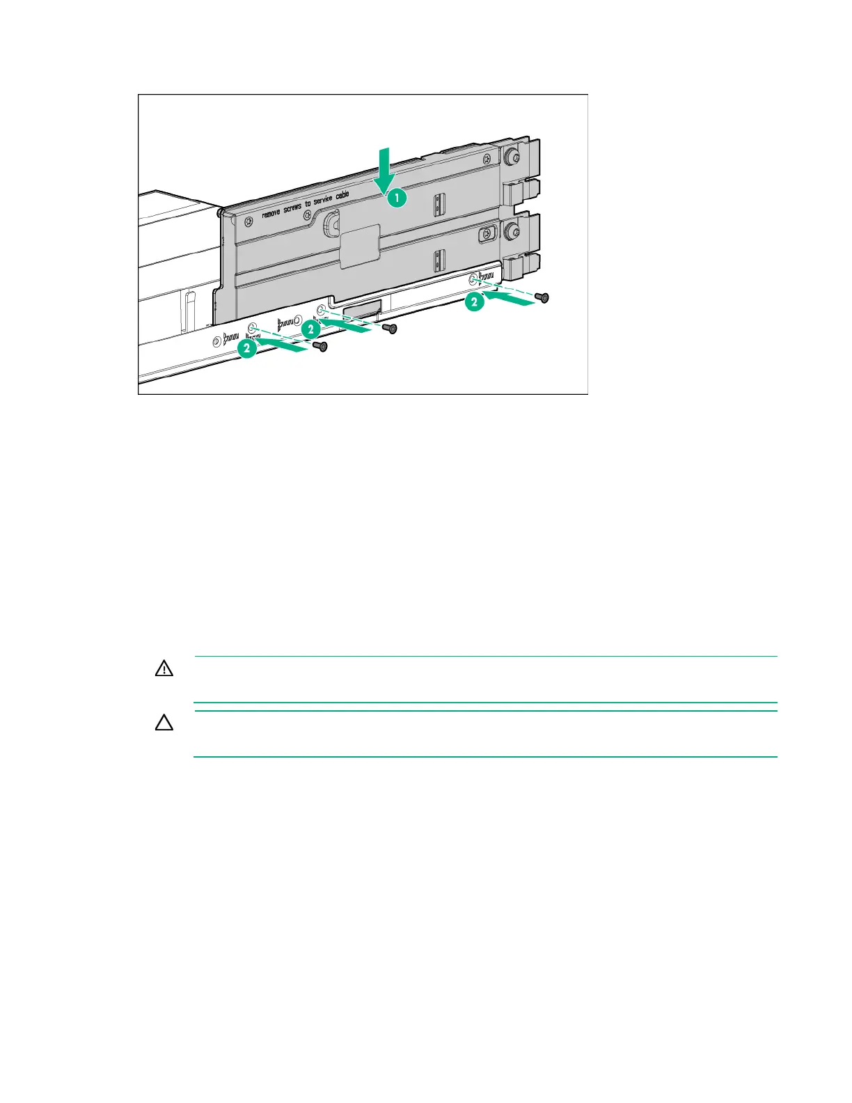
2U bayonet board assembly
.
4. If any SATA or mini-SAS cables are installed, secure the cables under the thin plastic cover along
the side of the node tray.
5. If removed, connect the B140i SATA cable to the system board ("SATA and mini-SAS cabling" on
page 140).
6. If an accelerator power cable was removed, connect it to the bayonet board ("Accelerator cabling" on
page 144).
7. Install any removed PCI riser cage assemblies ("PCI riser cage assembly options" on page 84).
8. Install the node into the chassis ("Installing a node into the chassis" on page 60).
9. Connect all peripheral cables to the node.
10. Power up the node ("Power up the nodes" on page 32).
Remove the PCI riser cage assembly
WARNING: To reduce the risk of personal injury from hot surfaces, allow the drives and the
internal system components to cool before touching them.
CAUTION: To prevent damage to the server or expansion boards, power down the server,
and disconnect all power cords before removing or installing the PCI riser cage.
Single-slot left PCI riser cage assembly
To remove the component:
1. Power down the node (on page 32).
2. Disconnect all peripheral cables from the node.
3. Remove the node from the chassis (on page 32).
4. Place the node on a flat, level surface.
5. In a 2U node, remove the three-slot riser cage assembly ("Three-slot riser cage assemblies" on page
52).
6. Remove the single-slot left PCI riser cage assembly: