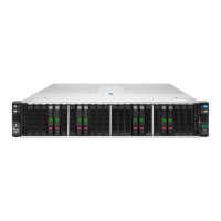
Component identification 19
• Node 3 corresponds to drive bays 3-1 through 4-3.
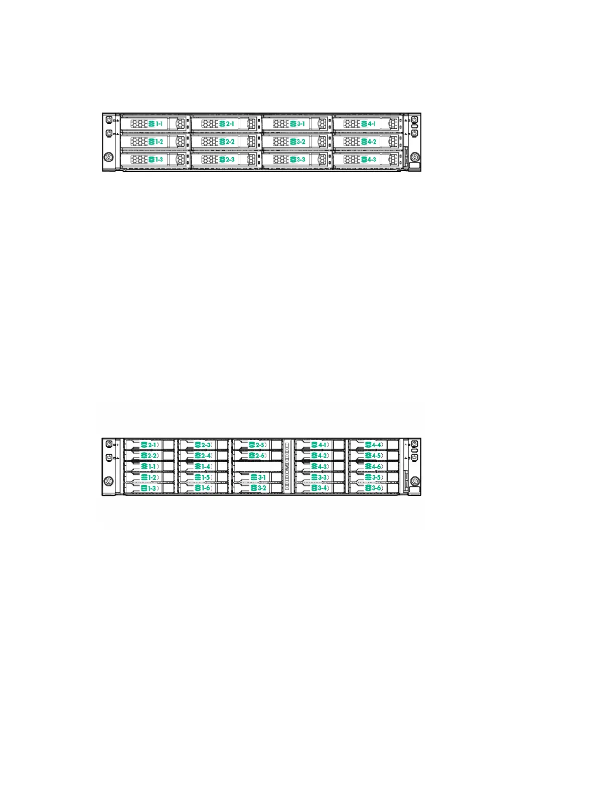
HPE Apollo r2600 Chassis drive bay numbering
One 1U node corresponds to a maximum of six SFF SmartDrives.
• Node 1 corresponds to drive bays 1-1 through 1-6.
• Node 2 corresponds to drive bays 2-1 through 2-6.
• Node 3 corresponds to drive bays 3-1 through 3-6.
• Node 4 corresponds to drive bays 4-1 through 4-6.
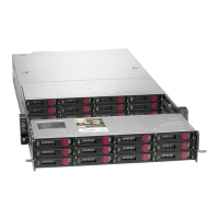
If a P840 Smart Array controller is installed, one 2U node corresponds to a maximum of twelve SFF
SmartDrives.
• Node 1 corresponds to drive bays 1-1 through 2-6.
• Node 3 corresponds to drive bays 3-1 through 4-6.
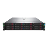
If using the Dynamic Smart Array B140i Controller, HPE H240 Host Bus Adapter, or HPE P440 Smart
Array Controller: one 2U node corresponds to a maximum of eight SFF SmartDrives. The remaining
drives bays must be populated with drive blanks.
• Node 1 corresponds to drive bays 1-1, 1-2, 1-4, 1-5, 2-1, 2-2, 2-3 and 2-5.