Hardware options installation 86
a.
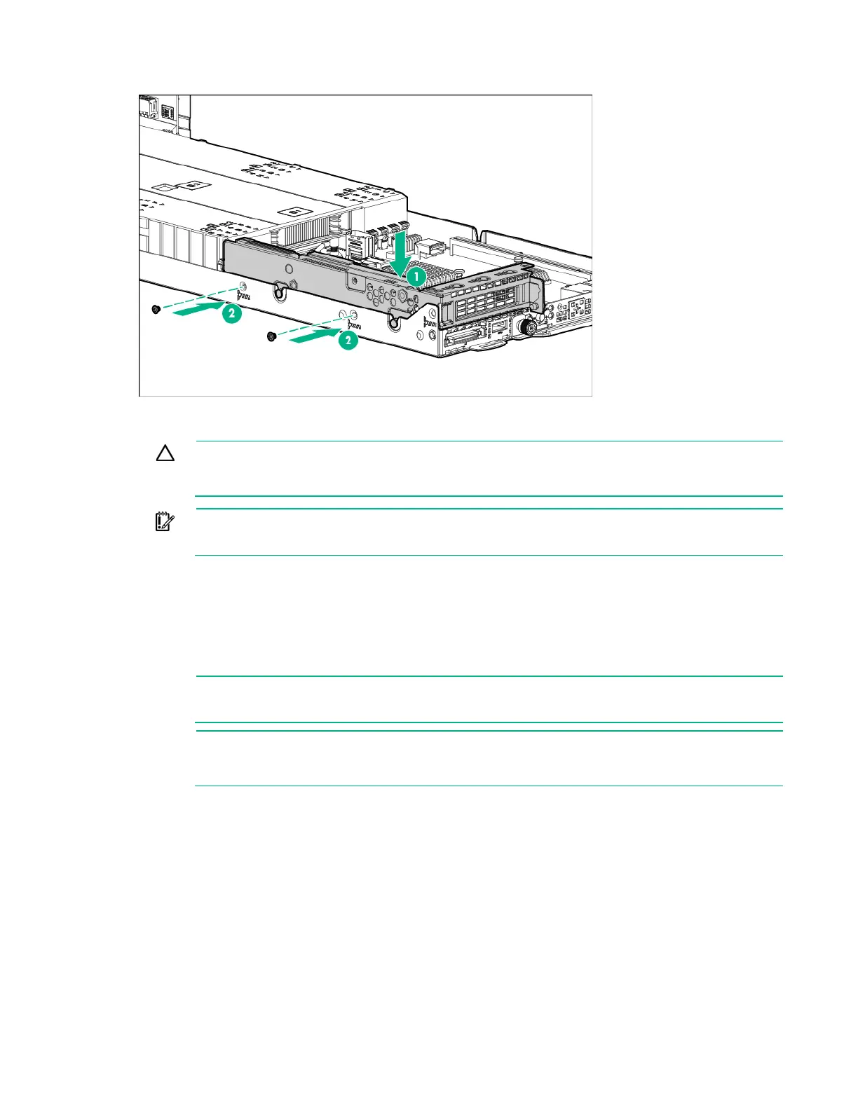
Install the single-slot left PCI riser cage assembly and then secure it with two T-10 screws.
b. Install the three-slot riser cage assembly and then secure it with six T-10 screws ("Three-slot
riser cage assembly options" on page 93).
CAUTION: To prevent improper cooling and thermal damage, do not operate the node
unless
all PCI riser cages or rear I/O blanks are installed, and do not operate the node unless all PCI
slots have either an expansion slot cover or an expansion board installed.
IMPORTANT: If the PCIe riser cage assembly is not seated properly, then the server does
not power up.
11. Install the node into the chassis ("Installing a node into the chassis" on page 60).
12. Connect all peripheral cables to the nodes.
13. Power up the node ("Power up the nodes" on page 32).
Single-slot 1U node right PCI riser cage assembly options
NOTE: If installing the Single-slot 1U right PCI riser cage assembly for Processor 2 (PN
798182-B21), a second processor is required.
NOTE: Single-
slot 1U node right PCI riser cage assemblies feature different riser boards. For
more information on the riser board slot specifications, see "PCIe riser board slot definitions
(on page 26)."
To install the component:
1. Power down the node (on page 32).
2. Disconnect all peripheral cables from the node.
3. Remove the node from the chassis (on page 32).
4. Place the node on a flat, level surface.
5. If installed, remove the single-slot left PCI riser cage assembly ("Single-slot left PCI riser cage
assembly" on page 48).
6. Remove the rear I/O blanks ("Remove the rear I/O blank" on page 39).