EasyManuals Logo

HPE Apollo 2000 User Manual

HPE Apollo 2000
187 pages
To Next Page IconTo Next Page
To Previous Page IconTo Previous Page
Page #20 background imageLoading...
Page #20 background image
Component identification 20
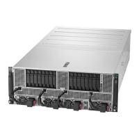
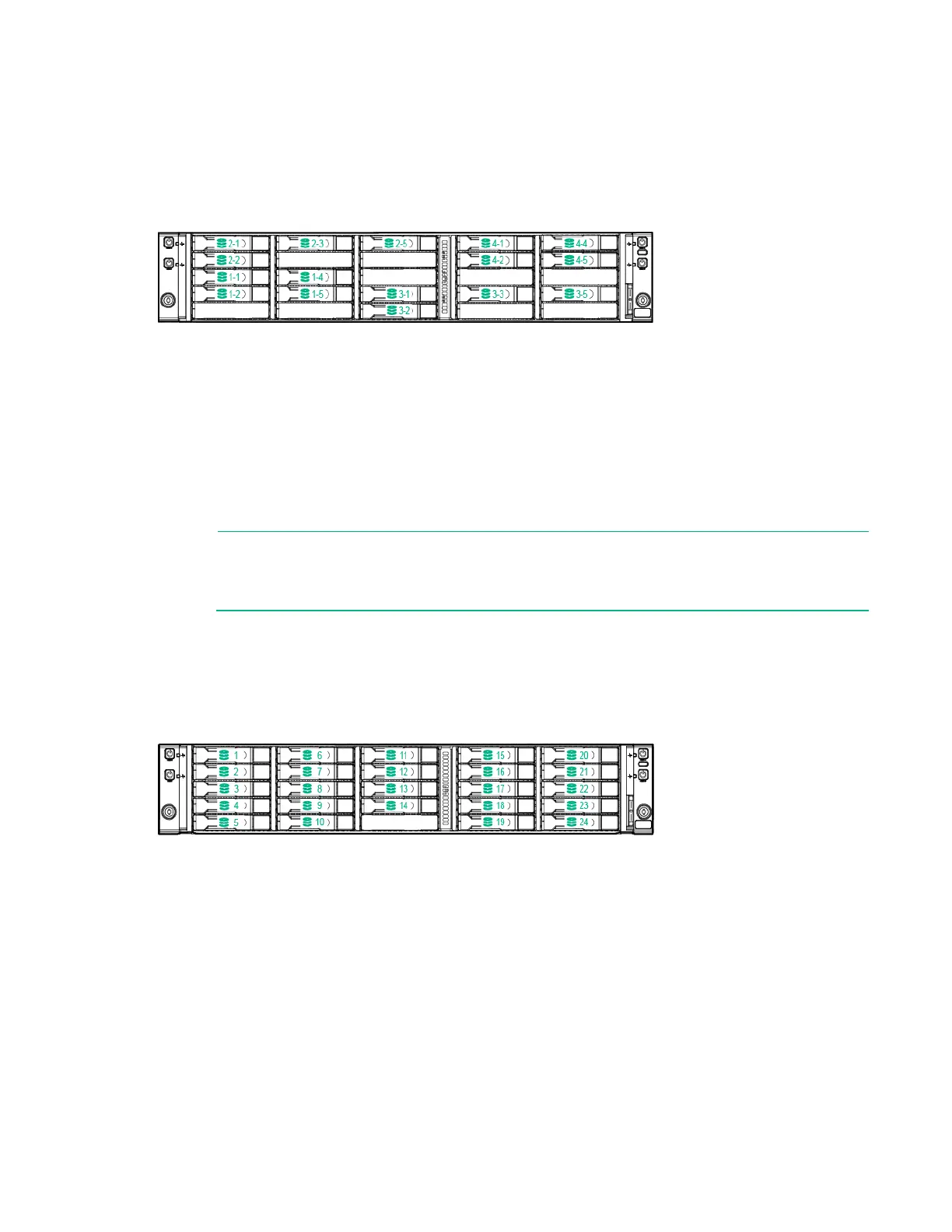
Node 3 corresponds to drive bays 3-1, 3-2, 3-3, 3-5, 4-1, 4-2, 4-4 and 4-5.
For more information on installing a storage controller, see "Controller options (on page 96)."
HPE Apollo r2800 Chassis drive bay numbering
IMPORTANT: The HPE Apollo r2800 Chassis does not support nodes using the HPE
Dynamic Smart Array B140i Controller or the HPE P840 Smart Array Controller. Hewlett
Packard Enterprise recommends installing an HPE H240 Host Bus Adapter or HPE P440
Smart Array Controller.
For information on drive bay mapping in the HPE Apollo r2800 Chassis and the factory default
configuration, see "Drive bay mapping for the HPE Apollo r2800 Chassis (on page 65)."
For more information on installing a storage controller, see "Controller options (on page 96)."

Table of Contents

Questions and Answers:

Question and Answer IconNeed help?

Do you have a question about the HPE Apollo 2000 and is the answer not in the manual?

HPE Apollo 2000 Specifications

General IconGeneral
Form Factor2U
Memory TypeDDR4
Max Processors2
Memory Slots16 DIMM slots per server tray
Storage OptionsSAS, SATA
NetworkingFlexibleLOM
Network1/10/25/40/100 GbE options
Power SupplyRedundant Power Supplies
Power Supply Options1600W
Operating System SupportMicrosoft Windows Server, Red Hat Enterprise Linux, SUSE Linux Enterprise Server, VMware
StorageUp to 24 drives

Related product manuals