Hardware options installation 84
o
2U bayonet board
9. Install the bayonet board bracket and bayonet board assembly ("Install the bayonet board assembly"
on page 45).
10. If installing a host bus adapter or Smart Array controller, install it into the riser cage ("Controller
options" on page 96).
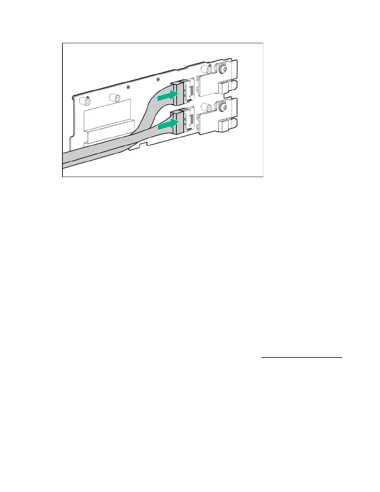
11. Do one of the following:
o Connect the B140i SATA cable to the system board.
o Connect all necessary internal cables to the storage controller.
For internal cabling information, see "SATA and Mini-SAS cabling (on page 140)."
12. Route and secure the cables under the thin plastic cover along the side of the node tray.
13. Install any removed PCI riser cage assemblies ("PCI riser cage assembly options" on page 84).
14. Install the node into the chassis ("Installing a node into the chassis" on page 60).
15. Connect all peripheral cables to the nodes.
16. Power up the node ("Power up the nodes" on page 32).
PCI riser cage assembly options
For more information on the riser board slot specifications, see "PCIe riser board slot definitions (on page
26)."
For more information about product features, specifications, options, configurations, and compatibility,
see the product QuickSpecs on the Hewlett Packard Enterprise website (http://www.hpe.com/info/qs).
Single-slot left PCI riser cage assembly option
To install the component:
1. Power down the node (on page 32).
2. Disconnect all peripheral cables from the node.
3. Remove the node from the chassis (on page 32).
4. Place the node on a flat, level surface.
5. Remove the rear I/O blank (on page 39).