Hardware options installation 83
If using the Dynamic Smart Array B140i Controller, the B140i 1U node SATA cable (PN 800060-B21) or
B140i 2U node SATA cable (PN 800061-B21) must be installed.
To install a P840 Smart Array controller in a 2U node, two P440/P840 Mini-SAS cable options (PN
798205-B21) are required.
For more information on the riser board slot specifications, see "PCIe riser board slot definitions (on page
26)."
For more information about product features, specifications, options, configurations, and compatibility,
see the product QuickSpecs on the Hewlett Packard Enterprise website (http://www.hpe.com/info/qs).
To connect the cable option:
1. Power down the node (on page 32).
2. Disconnect all peripheral cables from the node.
3. Remove the node from the chassis (on page 32).
4. Place the node on a flat, level surface.
5. If installed, remove the rear I/O blanks ("Remove the rear I/O blank" on page 39).
6. Remove any installed PCI riser cage assemblies ("Remove the PCI riser cage assembly" on page
48).
7. Remove the bayonet board assembly and bayonet bracket ("Remove the bayonet board assembly"
on page 43).
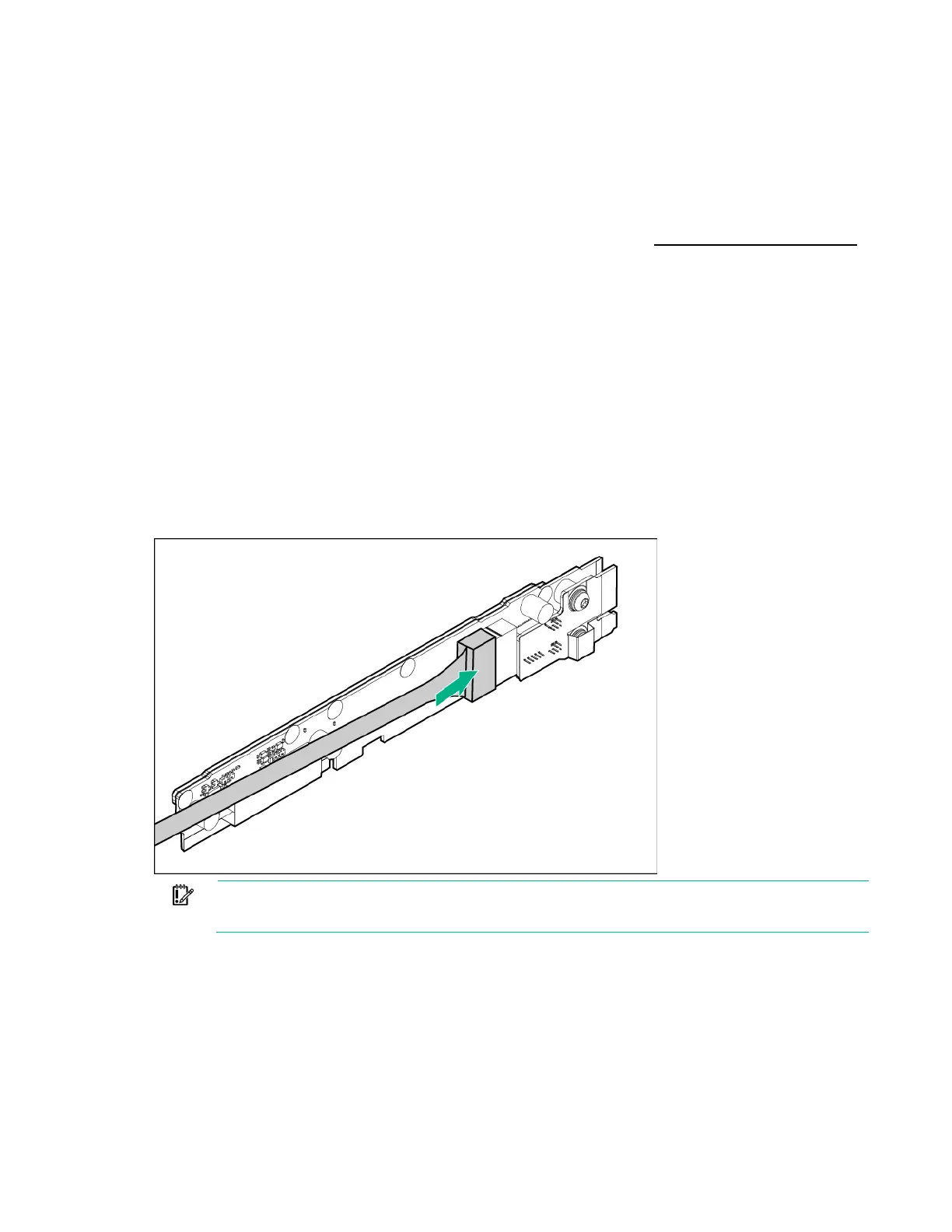
8. Connect the SATA or Mini-SAS cable to the bayonet board.
o 1U bayonet board
IMPORTANT: If connecting a SATA or Mini-SAS cable to the 2U bayonet board, route the
cable under the padding before installing the 2U bayonet board bracket.