91
Route Pinning : Disabled
Retry Limit : 10 Retry Interval : 2 sec
Reoptimization : Disabled Reoptimization Freq : -
Backup Type : None Backup LSP ID : -
Auto Bandwidth : Disabled Auto Bandwidth Freq : -
Min Bandwidth : - Max Bandwidth : -
Collected Bandwidth : -
# Execute the display ip routing-table command on Switch A. The output shows a static route entry
with interface Tunnel 1 as the output interface. (Details not shown.)
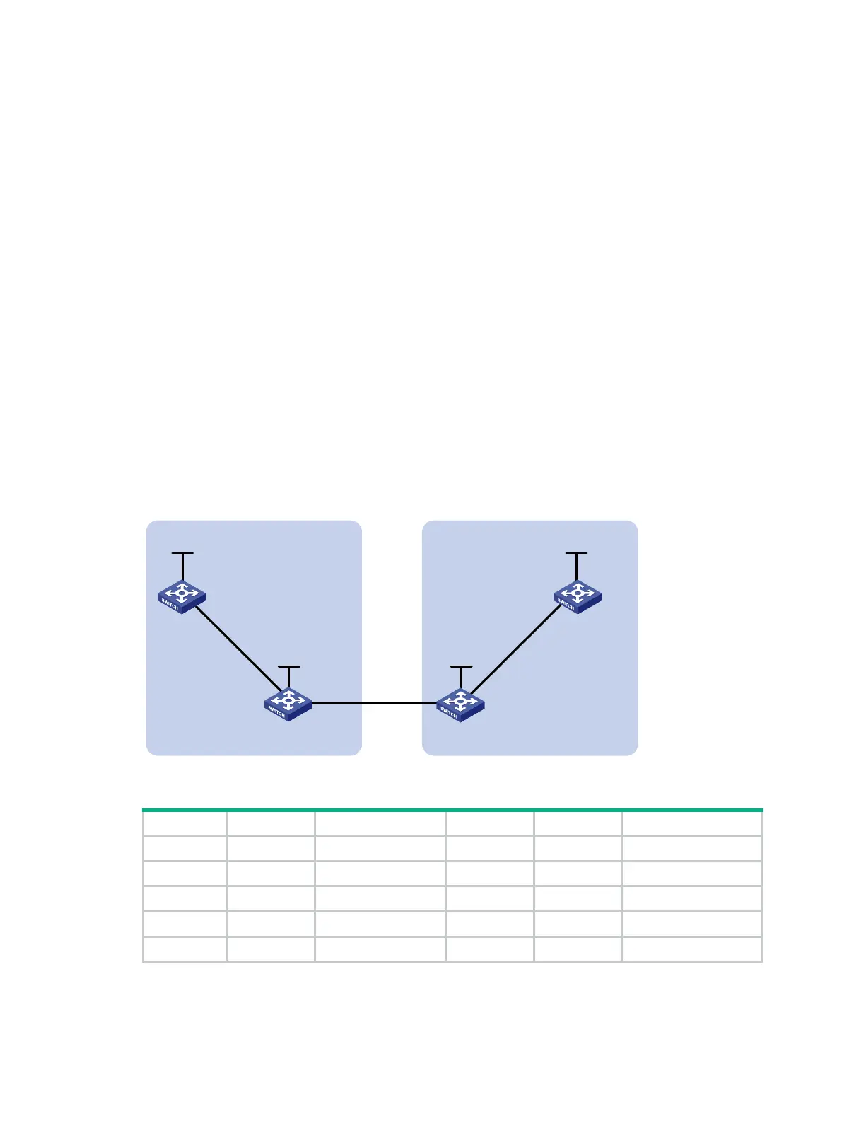
Establishing an inter-AS MPLS TE tunnel with RSVP-TE
Network requirements
Switch A and Switch B are in AS 100. Switch C and Switch D are in AS 200. AS 100 and AS 200 use
OSPF as the IGP.
Establish an EBGP connection between ASBRs Switch B and Switch C. Redistribute BGP routes
into OSPF and OSPF routes into BGP, so that a route is available between AS 100 and AS 200.
Establish an MPLS TE tunnel from Switch A to Switch D. The tunnel requires a bandwidth of 2000
kbps. The maximum bandwidth of the link that the tunnel traverses is 10000 kbps and the maximum
reservable bandwidth of the link is 5000 kbps.
Figure 29 Network diagram
Table 4 Interface and IP address assignment
Switch A Loop0 1.1.1.9/32 Switch D Loop0 4.4.4.9/32
Vlan-int1 10.1.1.1/24 Vlan-int3 30.1.1.2/24
Switch B Loop0 2.2.2.9/32 Switch C Loop0 3.3.3.9/32
Vlan-int1 10.1.1.2/24 Vlan-int3 30.1.1.1/24
Vlan-int2 20.1.1.1/24 Vlan-int2 20.1.1.2/24
Configuration procedure
1. Configure IP addresses and masks for interfaces. (Details not shown.)
MPLS backbone
AS 100
MPLS backbone
AS 200
Vlan-
int1
Vlan
-int1
Vlan-int2
Vlan-int2
Vlan-int3
Vlan-int3
Loop0
Loop0
Loop0
Loop
0
Switch A
Switch B
Switch C
Switch D

 Loading...


