375
LDP PW configuration example
Network requirements
Configure VPLS on each PE, and establish LDP PWs between the PEs to interconnect the CEs.
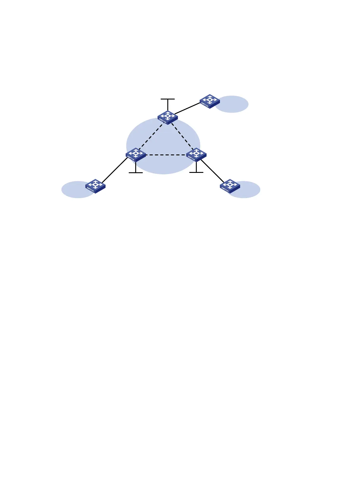
Figure 100 Network diagram
Configuration procedure
1. Configure an IGP and public tunnels on each PE. (Details not shown.)
2. Configure PE 1:
# Configure basic MPLS.
<PE1> system-view
[PE1] interface loopback 0
[PE1-LoopBack0] ip address 1.1.1.9 32
[PE1-LoopBack0] quit
[PE1] mpls lsr-id 1.1.1.9
[PE1] mpls ldp
[PE1-ldp] quit
# Enable L2VPN.
[PE1] l2vpn enable
# Configure VSI aaa that uses LDP as the PW signaling protocol, and establish a PW to PE 2
and PE 3, respectively.
[PE1] vsi aaa
[PE1-vsi-aaa] pwsignaling ldp
[PE1-vsi-aaa-ldp] peer 2.2.2.9 pw-id 500
[PE1-vsi-aaa-ldp-2.2.2.9-500] quit
[PE1-vsi-aaa-ldp] peer 3.3.3.9 pw-id 500
[PE1-vsi-aaa-ldp-3.3.3.9-500] quit
[PE1-vsi-aaa-ldp] quit
[PE1-vsi-aaa] quit
# Create Ethernet service instance 10 on GigabitEthernet 1/0/1 to match all packets.
[PE1] interface gigabitethernet1/0/1
[PE1-GigabitEthernet1/0/1] service-instance 10
[PE1-GigabitEthernet1/0/1-srv10] encapsulation default
Loop0
1.1.1.9/32
GE1/0/1 GE1/0/1
CE 1
VPN 1
PE 1
PE 2
Loop0
2.2.2.9/32
CE 2
VPN 1
Loop0
3.3.3.9/32
PE 3
CE 3
VPN 1
GE1/0/1
Vlan-int20 Vlan-int20
Vlan-int30
Vlan-int30 Vlan-int40
Vlan-int40
 Loading...


