253
OSPF Process 100 with Router ID 100.1.1.2
Sham link
Area Neighbor ID Source IP Destination IP State Cost
0.0.0.1 120.1.1.2 3.3.3.3 5.5.5.5 P-2-P 10
# Verify that the peer state is Full on PE 1.
[PE1] display ospf sham-link area 1
OSPF Process 100 with Router ID 100.1.1.2
Sham-Link: 3.3.3.3 --> 5.5.5.5
Neighbor ID: 120.1.1.2 State: Full
Area: 0.0.0.1
Cost: 10 State: P-2-P Type: Sham
Timers: Hello 10, Dead 40, Retransmit 5, Transmit Delay 1
Request list: 0 Retransmit list: 0
Configuring BGP AS number substitution
Network requirements
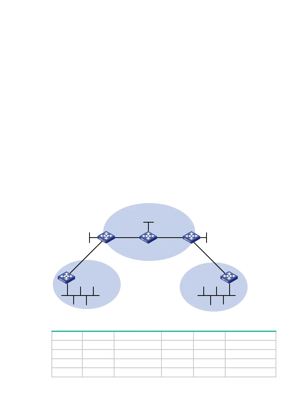
As shown in Figure 71, CE 1 and CE 2 belong to VPN 1 and are connected to PE 1 and PE 2,
respectively. The two CEs have the same AS number, 600. Configure BGP AS number substitution
on the PEs to enable the CEs to communicate with each other.
Figure 71 Network diagram
Table 21 Interface and IP address assignment
CE 1 Vlan-int11 10.1.1.1/24 P Loop0 2.2.2.9/32
Vlan-int12 100.1.1.1/24 Vlan-int11 30.1.1.1/24
PE 1 Loop0 1.1.1.9/32 Vlan-int12 20.1.1.2/24
Vlan-int11 10.1.1.2/24 PE 2 Loop0 3.3.3.9/32
Loop0
Loop
0 Loop0
PE 1
P
PE 2
CE 1
CE 2
VPN 1
AS 600
VPN 1
AS 600
Vlan-int12
MPLS backbone
AS 100
Vlan-int12 Vlan-int11
Vlan-int13
Vlan-int12
Vlan-int11
Vlan-int12
Vlan-int12
Vlan-int11
Vlan-int11

 Loading...