286
NextHop : :: Preference: 0
Interface : NULL0 Cost : 0
Destination: FF00::/8 Protocol : Direct
NextHop : :: Preference: 0
Interface : NULL0 Cost : 0
The output shows that PE 1 has routes to the remote CEs. Output on PE 2 is similar.
# Verify that CEs of the same VPN can ping each other, and CEs of different VPNs cannot ping each
other. For example, CE 1 can ping CE 3 (2001:3::1), but cannot ping CE 4 (2001:4::1). (Details not
shown.)
Configuring IPv6 MPLS L3VPN inter-AS option A
Network requirements
CE 1 and CE 2 belong to the same VPN. CE 1 accesses the network through PE 1 in AS 100, and
CE 2 accesses the network through PE 2 in AS 200.
Configure IPv6 MPLS L3VPN inter-AS option A, and use the VRF-to-VRF method to manage VPN
routes.
Run OSPF on the MPLS backbone of each AS.
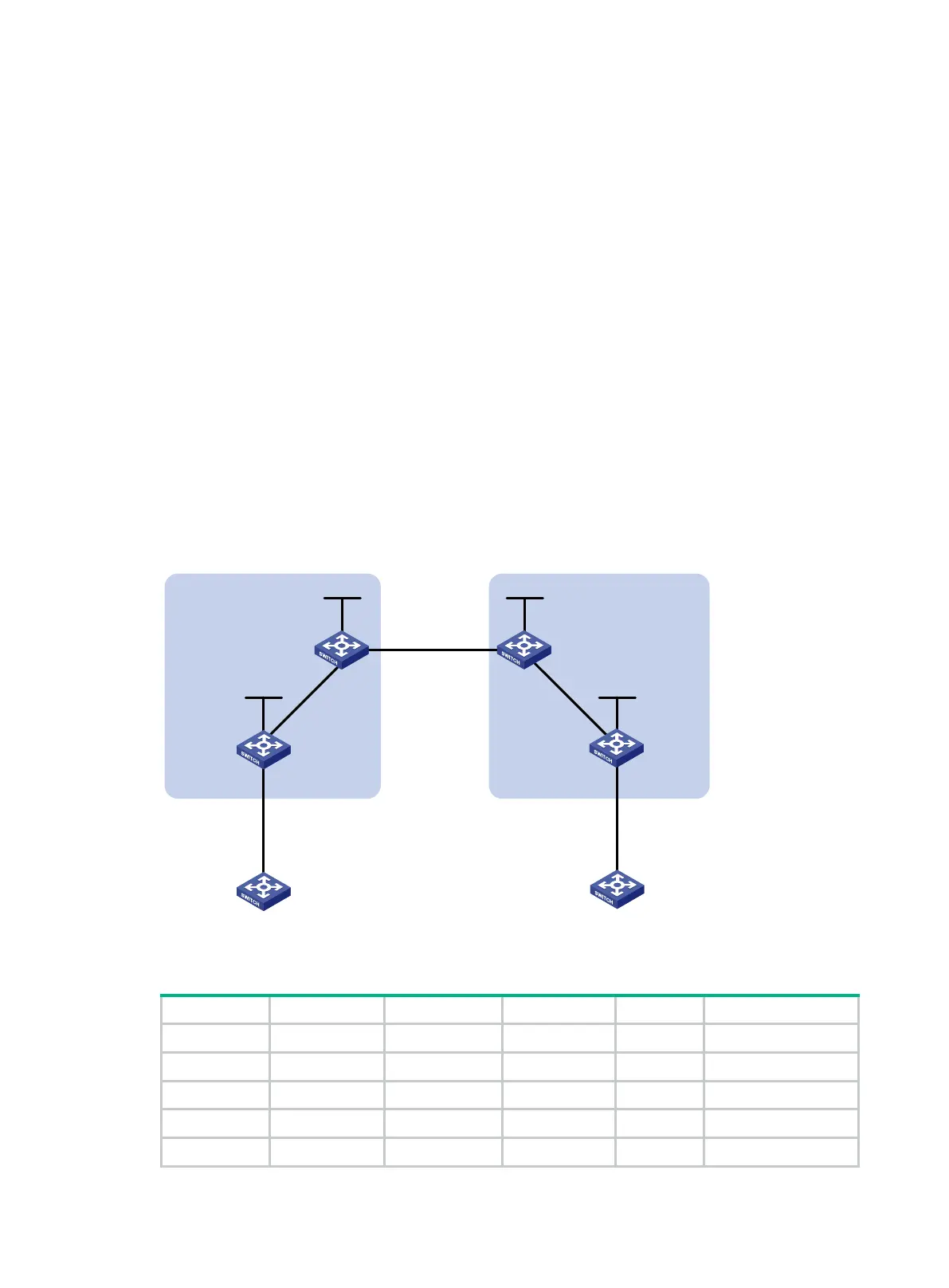
Figure 78 Network diagram
Table 26 Interface and IP address assignment
CE 1 Vlan-int12 2001:1::1/96 CE 2 Vlan-int12 2001:2::1/96
PE 1 Loop0 1.1.1.9/32 PE 2 Loop0 4.4.4.9/32
Vlan-int12 2001:1::2/96 Vlan-int12 2001:2::2/96
Vlan-int11 172.1.1.2/24 Vlan-int11 162.1.1.2/24
ASBR-PE 1 Loop0 2.2.2.9/32 ASBR-PE 2 Loop0 3.3.3.9/32
Loop0 Loop0
Loop0 Loop0
Vlan-int12
CE 1 CE 2
AS 65001 AS 65002
PE 1
PE 2
ASBR-PE 2
ASBR-PE 1
MPLS backbone
MPLS backbone
AS 100
AS 200
Vlan-int12
Vlan-int12
Vlan-int12
Vlan-int11
Vlan-int11
Vlan-int12Vlan-int12
Vlan-int11
Vlan-int11

 Loading...


