249
# Advertise to UPE 2 the routes permitted by a routing policy (the routes of CE 1).
[SPE2] ip prefix-list hope index 10 permit 10.2.1.1 24
[SPE2] route-policy hope permit node 0
[SPE2-route-policy-hope-0] if-match ip address prefix-list hope
[SPE2-route-policy-hope-0] quit
[SPE2] bgp 100
[SPE2-bgp] address-family vpnv4
[SPE2-bgp-vpnv4] peer 4.4.4.9 upe route-policy hope export
Verifying the configuration
# Verify that CE 1 and CE3 can learn each other's interface routes and can ping each other. CE 2 and
CE 4 cannot learn each other's interface routes and cannot ping each other. (Details not shown.)
Configuring an OSPF sham link
Network requirements
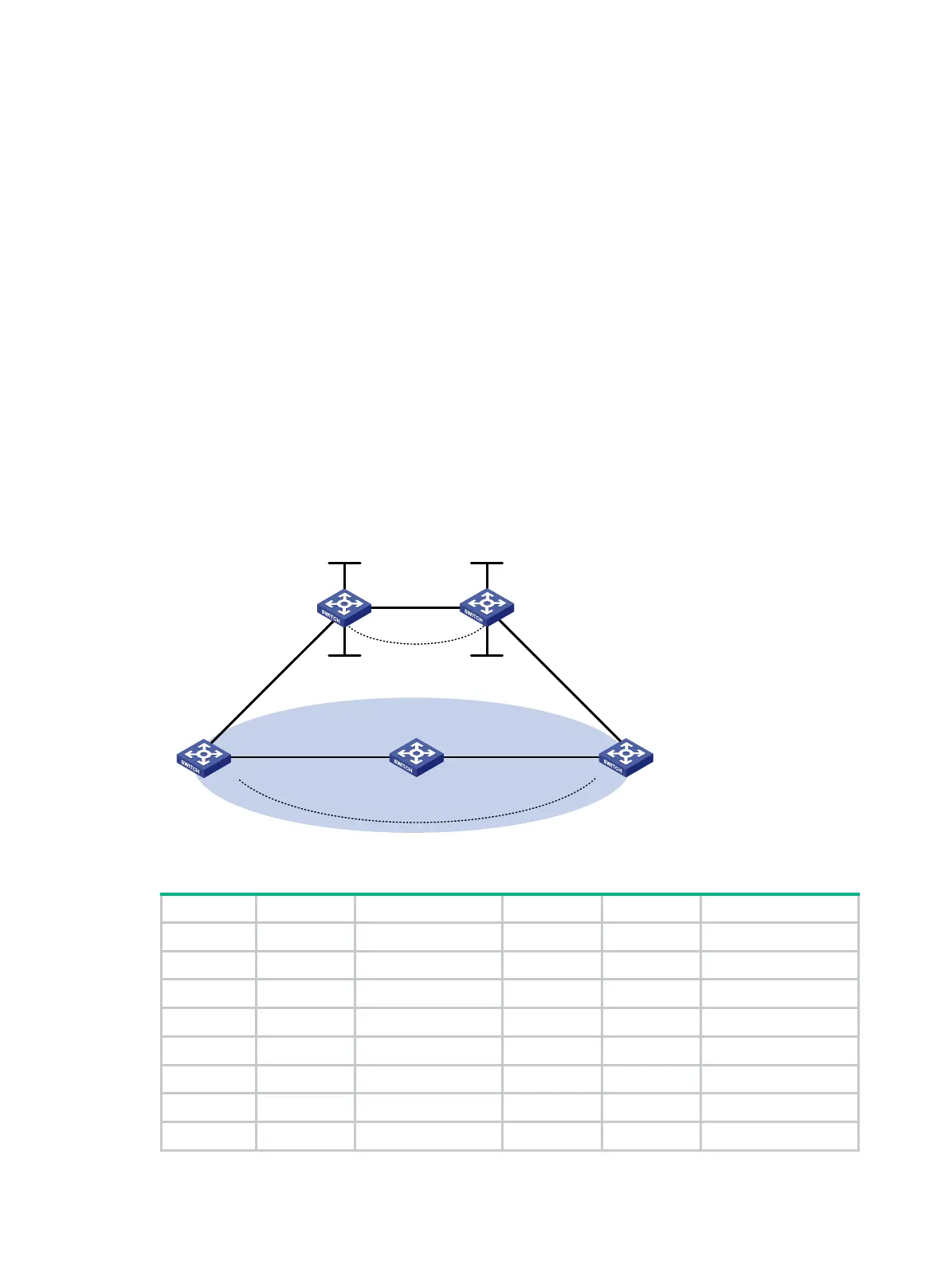
As shown in Figure 70, CE 1 and CE 2 belong to VPN 1. Configure an OSPF sham link between PE
1 and PE 2 so traffic between CE 1 and CE 2 is forwarded through the MPLS backbone, instead of
the backdoor link.
Figure 70 Network diagram
Table 20 Interface and IP address assignment
CE 1 Vlan-int11 100.1.1.1/24 CE 2 Vlan-int11 120.1.1.1/24
Vlan-int13 20.1.1.1/24 Vlan-int12 30.1.1.2/24
PE 1 Loop0 1.1.1.9/32 PE 2 Loop0 2.2.2.9/32
Loop1 3.3.3.3/32 Loop1 5.5.5.5/32
Vlan-int11 100.1.1.2/24 Vlan-int11 120.1.1.2/24
Vlan-int12 10.1.1.1/24 Vlan-int12 10.1.1.2/24
Switch A Vlan-int11 20.1.1.2/24
Vlan-int12 30.1.1.1/24
Vlan
-
int
12
Loop0
Loop
0
Sham
-
link
CE
1
Switch A
CE 2
PE 2
PE
1
Loop
1
Loop1
OSPF Area
1
Backdoor link
Vlan
-
int
12
Vlan-
int
11
Vlan-
int11
Vlan
-int13
Vlan
-
int11
Vlan-
int
11
Vlan-
int
12 Vlan
-
int
12
Vlan-
int13

 Loading...


