259
Cost: 0 Preference: 255
IpPre: N/A QosLocalID: N/A
Tag: 0 State: Active Adv
OrigTblID: 0x0 OrigVrf: default-vrf
TableID: 0x102 OrigAs: 300
NibID: 0x15000002 LastAs: 300
AttrID: 0x2 Neighbor: 2.2.2.2
Flags: 0x110060 OrigNextHop: 2.2.2.2
Label: 1146 RealNextHop: 172.1.1.2
BkLabel: 1275 BkNextHop: 172.2.1.3
Tunnel ID: Invalid Interface: Vlan-int11
BkTunnel ID: Invalid BkInterface: Vlan-int12
FtnIndex: 0x0
Configuring MPLS L3VPN FRR through VPNv4 route backup
for an IPv4 route
Network requirements
CE 1 and CE 2 belong to VPN 1.
Configure EBGP between CEs and PEs to exchange VPN routes.
Configure OSPF to ensure connectivity between PEs, and configure MP-IBGP to exchange VPNv4
routing information between PEs.
Configure MPLS L3VPN FRR on PE 2 to achieve the following purposes:
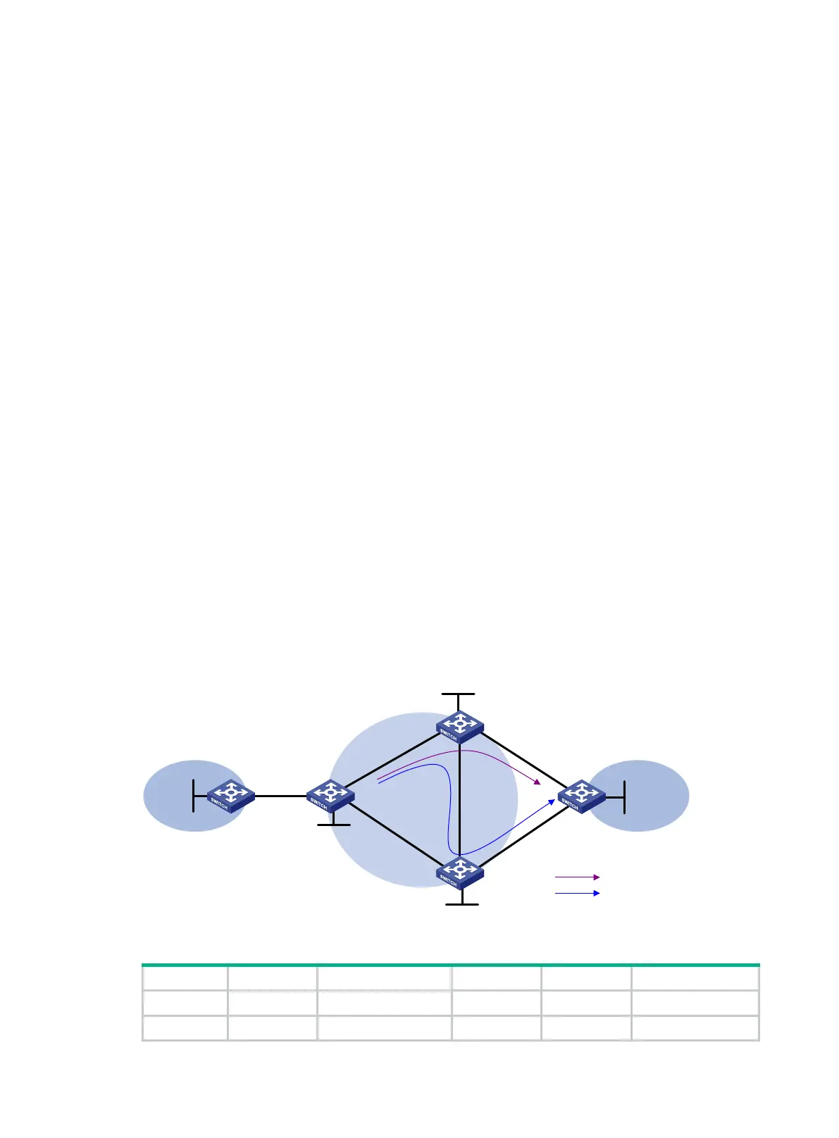
• When the link PE 2—CE 2 operates correctly, traffic from CE 1 to CE 2 goes through the path
CE 1—PE 1—PE 2—CE 2.
• When BFD detects that the link between PE 2 and CE 2 fails, traffic from CE 1 to CE 2 goes
through the path CE 1—PE 1—PE 2—PE 3—CE 2.
Figure 73 Network diagram
Table 23 Interface and IP address assignment
CE 1 Loop0 5.5.5.5/32 PE 2 Loop0 2.2.2.2/32
Vlan-int10 10.2.1.1/24
Vlan-int11 172.1.1.2/24
CE 2
CE 1
VPN 1
VPN 1
MPLS
backbone
PE 2
PE 1
PE
3
Vlan-int13
Vlan-int14
Vlan-int13Vlan-int11
Vlan-int14Vlan-int12
Vlan-int11
Vlan-int12
Vlan-int10
Vlan-int10
Loop0
Loop0
Loop0
Loop0
Vlan-int15
Vlan-int15
Loop0
Primary link
Backup link

 Loading...


