161
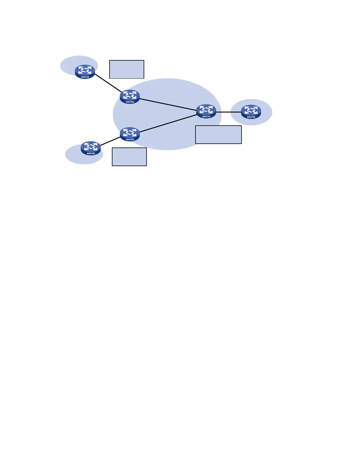
Figure 45 Network diagram for extranet networking scheme
As shown in Figure 45, route targets configured on PEs produce the following results:
• PE 3 can receive VPN-IPv4 routes from PE 1 and PE 2.
• PE 1 and PE 2 can receive VPN-IPv4 routes advertised by PE 3.
• Site 1 and Site 3 of VPN 1 can communicate with each other, and Site 2 of VPN 2 and Site 3 of
VPN 1 can communicate with each other.
• PE 3 advertises neither the VPN-IPv4 routes received from PE 1 to PE 2 nor the VPN-IPv4
routes received from PE 2 to PE 1 (routes learned from an IBGP neighbor are not advertised to
any other IBGP neighbor). Therefore, Site 1 of VPN 1 and Site 2 of VPN 2 cannot communicate
with each other.
Inter-AS VPN
In an inter-AS VPN networking scenario, multiple sites of a VPN are connected to multiple ISPs in
different ASs, or to multiple ASs of an ISP.
The following inter-AS VPN solutions are available:
• VRF-to-VRF connections between ASBRs—This solution is also called inter-AS option A.
• EBGP redistribution of labeled VPN-IPv4 routes between ASBRs—ASBRs advertise
VPN-IPv4 routes to each other through MP-EBGP. This solution is also called inter-AS option B.
• Multihop EBGP redistribution of labeled VPN-IPv4 routes between PE routers—PEs
advertise VPN-IPv4 routes to each other through MP-EBGP. This solution is also called
inter-AS option C.
Inter-AS option A
In this solution, PEs of two ASs are directly connected, and each PE is also the ASBR of its AS. Each
PE treats the other as a CE and advertises unlabeled IPv4 unicast routes through EBGP. The PEs
associate a VPN instance with at least one interface.
CE
CE
PE 1
PE 3
Site 2
Site 1
Site 3
VPN 1
VPN 1
VPN 2
VPN 1:
Import:100:1
Export:100:1
CE
VPN 2:
Import:200:1
Export:200:1
PE 2
VPN 1:
Import:100:1,200:1
Export:100:1,200:1

 Loading...


