327
[CE2-GigabitEthernet1/0/1] quit
Verifying the configuration
# Display L2VPN PW information on PE 1. The output shows that a static PW has been established.
[PE1] display l2vpn pw
Flags: M - main, B - backup, H - hub link, S - spoke link, N - no split horizon
Total number of PWs: 1, 1 up, 0 blocked, 0 down, 0 defect
Xconnect-group Name: vpna
Peer PW ID In/Out Label Proto Flag Link ID State
192.3.3.3 3 100/200 Static M 0 Up
# Display L2VPN PW information on PE 2. The output shows that a static PW has been established.
[PE2] display l2vpn pw
Flags: M - main, B - backup, H - hub link, S - spoke link, N - no split horizon
Total number of PWs: 1, 1 up, 0 blocked, 0 down, 0 defect
Xconnect-group Name: vpna
Peer PW ID In/Out Label Proto Flag Link ID State
192.2.2.2 3 200/100 Static M 0 Up
# Verify that CE 1 and CE 2 can ping each other. (Details not shown.)
Configuring an LDP PW
Network requirements
Create an LDP PW between PE 1 and PE 2 over the backbone so VLAN 10 on CE 1 can
communicate with VLAN 10 on CE 2.
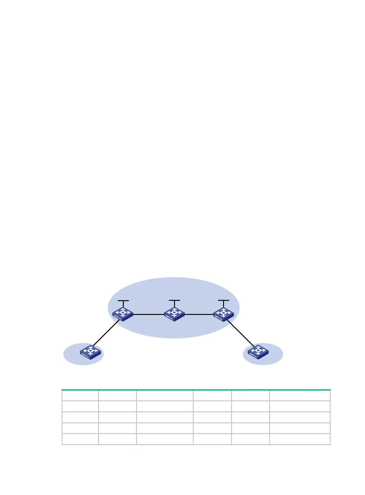
Figure 88 Network diagram
Table 30 Interface and IP address assignment
PE 1 Loop0 192.2.2.2/32 P Loop0 192.4.4.4/32
Vlan-int20 10.1.1.1/24 Vlan-int20 10.1.1.2/24
PE 2 Loop0 192.3.3.3/32 Vlan-int30 10.2.2.2/24
Vlan-int30 10.2.2.1/24
MPLS or IP backbone
CE 1 CE 2
PE 1 PE 2P
Vlan-int20
Vlan-int20
Vlan-int30
Vlan-int30
GE1/0/1 GE1/0/1
GE1/0/1
GE1/0/1
Loop0 Loop0 Loop0
Site 1 Site 2

 Loading...


