209
Configuring MPLS L3VPN inter-AS option A
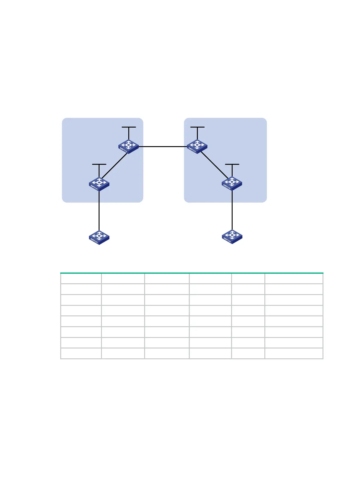
Network requirements
CE 1 and CE 2 belong to the same VPN. CE 1 accesses the network through PE 1 in AS 100, and
CE 2 accesses the network through PE 2 in AS 200.
Configure MPLS L3VPN inter-AS option A, and use the VRF-to-VRF method to manage VPN routes.
Run OSPF on the MPLS backbone in each AS.
Figure 64 Network diagram
Table 14 Interface and IP address assignment
CE 1 Vlan-int12 10.1.1.1/24 CE 2 Vlan-int12 10.2.1.1/24
PE 1 Loop0 1.1.1.9/32 PE 2 Loop0 4.4.4.9/32
Vlan-int12 10.1.1.2/24 Vlan-int12 10.2.1.2/24
Vlan-int11 172.1.1.2/24 Vlan-int11 162.1.1.2/24
ASBR-PE 1 Loop0 2.2.2.9/32 ASBR-PE 2 Loop0 3.3.3.9/32
Vlan-int11 172.1.1.1/24 Vlan-int11 162.1.1.1/24
Vlan-int12 192.1.1.1/24 Vlan-int12 192.1.1.2/24
Configuration procedure
1. Configure IGP on the MPLS backbone to implement the connectivity in the backbone:
This example uses OSPF. (Details not shown.)
# Execute the display ospf peer command to verify that each ASBR-PE has established an
OSPF adjacency in Full state with the PE in the same AS, and that PEs and ASBR-PEs in the
same AS have learned the routes to the loopback interfaces of each other. Verify that each
ASBR-PE and the PE in the same AS can ping each other. (Details not shown.)
2. Configure basic MPLS and MPLS LDP on the MPLS backbone to establish LDP LSPs:
Loop0 Loop0
Loop0 Loop0
Vlan-int12
CE 1 CE 2
AS 65001 AS 65002
PE 1
PE 2
ASBR-PE 2
ASBR-PE 1
MPLS backbone
MPLS backbone
AS 100
AS 200
Vlan-int12
Vlan-int12
Vlan-int12
Vlan-int11
Vlan-int11
Vlan-int12Vlan-int12
Vlan-int11
Vlan-int11

 Loading...


