257
200.1.1.0/24 Direct 0 0 200.1.1.1 Vlan13
200.1.1.0/32 Direct 0 0 200.1.1.1 Vlan13
200.1.1.1/32 Direct 0 0 127.0.0.1 InLoop0
200.1.1.255/32 Direct 0 0 200.1.1.1 Vlan13
224.0.0.0/4 Direct 0 0 0.0.0.0 NULL0
224.0.0.0/24 Direct 0 0 0.0.0.0 NULL0
255.255.255.255/32 Direct 0 0 127.0.0.1 InLoop0
# Verify that the VLAN interfaces of CE 1 and CE 2 can ping each other. (Details not shown.)
Configuring MPLS L3VPN FRR through VPNv4 route backup
for a VPNv4 route
Network requirements
CE 1 and CE 2 belong to VPN 1.
Configure EBGP between CEs and PEs to exchange VPN routes.
Configure OSPF to ensure connectivity between PEs, and configure MP-IBGP to exchange VPNv4
routing information between PEs.
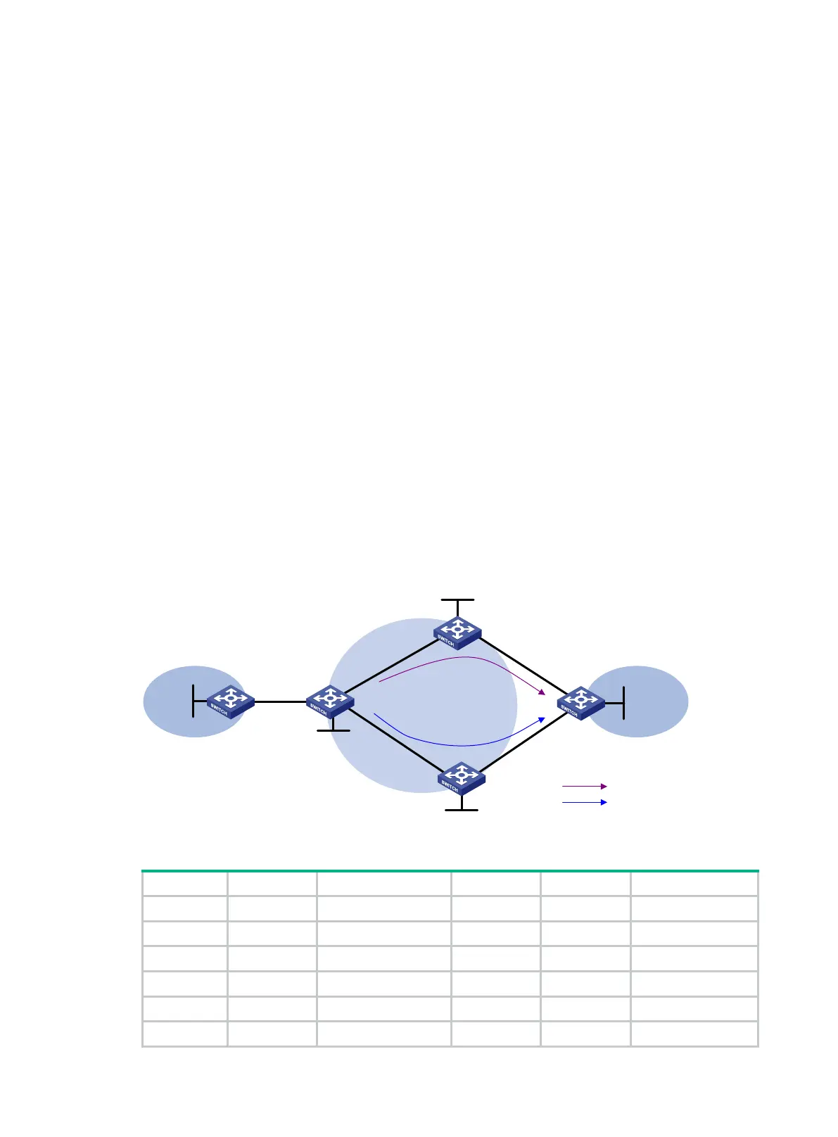
Configure MPLS L3VPN FRR on PE 1 to achieve the following purposes:
• When the link PE 1—PE 2 operates correctly, traffic from CE 1 to CE 2 goes through the path
CE 1—PE 1—PE 2—CE 2.
• When BFD detects that the LSP between PE 1 and PE 2 fails, traffic from CE 1 to CE 2 goes
through the path CE 1—PE 1—PE 3—CE 2.
Figure 72 Network diagram
Table 22 Interface and IP address assignment
CE 1 Loop0 5.5.5.5/32 PE 1 Loop0 1.1.1.1/32
Vlan-int10 10.2.1.1/24
Vlan-int10 10.2.1.2/24
PE 2 Loop0 2.2.2.2/32
Vlan-int11 172.1.1.1/24
Vlan-int11 172.1.1.2/24
Vlan-int12 172.2.1.1/24
Vlan-int13 10.1.1.2/24 CE 2 Loop0 4.4.4.4/32
PE 3 Loop0 3.3.3.3/32
Vlan-int13 10.1.1.1/24
CE 2
CE
1
VPN 1
VPN 1
MPLS backbone
PE 2
PE 1
PE 3
Vlan-int13
Vlan-int14
Vlan-int13Vlan-int11
Vlan-int14Vlan-int12
Vlan-int11
Vlan-int12
Vlan-int10
Vlan-int10
Loop0
Loop0
Loop0
Loop0
Primary link
Backup link
Loop
0

 Loading...


