98
1.1.1.9/32 Direct 0 0 127.0.0.1 InLoop0
2.2.2.9/32 OSPF 10 1 10.1.1.2 Vlan1
3.3.3.9/32 O_ASE 150 1 10.1.1.2 Vlan1
4.4.4.9/32 O_ASE 150 1 10.1.1.2 Vlan1
7.1.1.0/24 Direct 0 0 7.1.1.1 Tun1
7.1.1.1/32 Direct 0 0 127.0.0.1 InLoop0
10.1.1.0/24 Direct 0 0 10.1.1.1 Vlan1
10.1.1.1/32 Direct 0 0 127.0.0.1 InLoop0
20.1.1.0/24 O_ASE 150 1 10.1.1.2 Vlan1
30.1.1.0/24 Static 1 0 7.1.1.1 Tun1
127.0.0.0/8 Direct 0 0 127.0.0.1 InLoop0
127.0.0.1/32 Direct 0 0 127.0.0.1 InLoop0
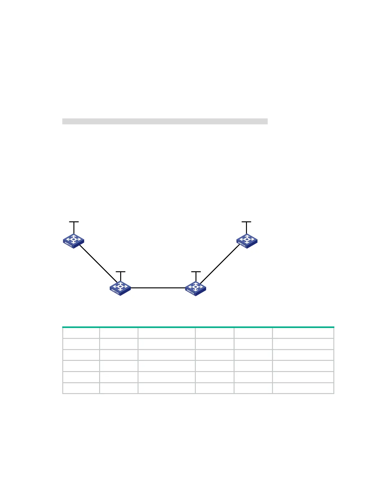
Bidirectional MPLS TE tunnel configuration example
Network requirements
Switch A, Switch B, Switch C, and Switch D all run IS-IS and they are all level-2 switches.
Use RSVP-TE to establish a bidirectional MPLS TE tunnel between Switch A and Switch D.
Figure 30 Network diagram
Table 5 Interface and IP address assignment
Switch A Loop0 1.1.1.9/32 Switch D Loop0 4.4.4.9/32
Vlan-int1 10.1.1.1/24 Vlan-int3 30.1.1.2/24
Switch B Loop0 2.2.2.9/32 Switch C Loop0 3.3.3.9/32
Vlan-int1 10.1.1.2/24 Vlan-int3 30.1.1.1/24
Vlan-int2 20.1.1.1/24 Vlan-int2 20.1.1.2/24
Configuration procedure
1. Configure IP addresses and masks for interfaces. (Details not shown.)
2. Configure IS-IS to advertise interface addresses, including the loopback interface address.
For more information, see "Establishing an MPLS TE tunnel with RSVP-TE."
3. Configure an LSR ID, and enable MPLS, MPLS TE, and RSVP-TE on each switch. Configure
Switch A and Switch D to assign a non-null label to the penultimate hop:
Vlan-int1
Vlan-int1
Vlan-int2
Vlan-int
2
Vlan-int3
Vlan
-int3
Loop
0
Loop0
Loop0
Loop0
Switch A
Switch B
Switch C
Switch D

 Loading...


