242
Configuring HoVPN
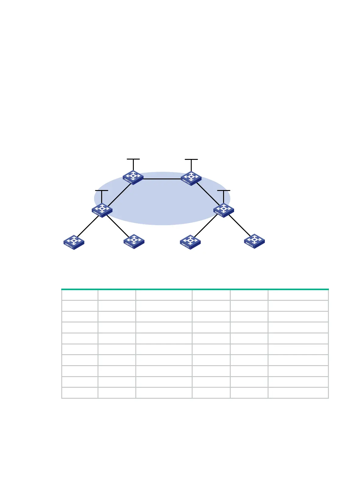
Network requirements
There are two levels of networks, the backbone and the MPLS VPN networks, as shown in Figure
69.
• SPEs act as PEs to allow MPLS VPNs to access the backbone.
• UPEs act as PEs of the MPLS VPNs to allow end users to access the VPNs.
• Performance requirements for the UPEs are lower than those for the SPEs.
• SPEs advertise routes permitted by the routing policies to UPEs, permitting CE 1 and CE 3 in
VPN 1 to communicate with each other, and forbidding CE 2 and CE 4 in VPN 2 from
communicating with each other.
Figure 69 Network diagram
Table 19 Interface and IP address assignment
CE 1 Vlan-int12 10.2.1.1/24 CE 3 Vlan-int12 10.1.1.1/24
CE 2 Vlan-int13 10.4.1.1/24 CE 4 Vlan-int13 10.3.1.1/24
UPE 1 Loop0 1.1.1.9/32 UPE 2 Loop0 4.4.4.9/32
Vlan-int11 172.1.1.1/24 Vlan-int11 172.2.1.1/24
Vlan-int12 10.2.1.2/24 Vlan-int12 10.1.1.2/24
Vlan-int13 10.4.1.2/24 Vlan-int13 10.3.1.2/24
SPE 1 Loop0 2.2.2.9/32 SPE 2 Loop0 3.3.3.9/32
Vlan-int11 172.1.1.2/24 Vlan-int11 172.2.1.2/24
Vlan-int12 180.1.1.1/24 Vlan-int12 180.1.1.2/24
Configuration procedure
1. Configure UPE 1:
# Configure basic MPLS and MPLS LDP to establish LDP LSPs.
<UPE1> system-view
[UPE1] interface loopback 0
SPE 1 SPE 2
UPE
1 UPE 2
CE 1 CE 2 CE 3 CE 4
Vlan-int12
Loop0 Loop0
AS 65410 AS 65420 AS
65430 AS 65440
Loop0Loop0
VPN
1 VPN
1
VPN 2 VPN 2
AS 100
Vlan-int12
Vlan-int
11
Vlan-int11
Vlan-int13
Vlan-int12
Vlan-int13
Vlan-int12
Vlan
-int12
Vlan-int13
Vlan-int13
Vlan-int12
Vlan-int11
Vlan-int
11

 Loading...


