339
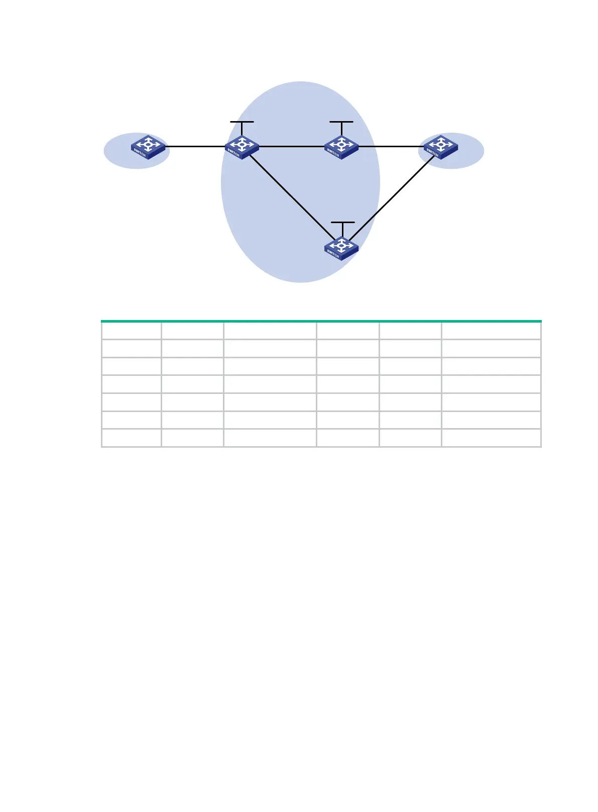
Figure 91 Network diagram
Table 33 Interface and IP address assignment
CE 1 Vlan-int10 100.1.1.1/24 PE 2 Loop0 2.2.2.2/32
PE 1 Loop0 1.1.1.1/32 Vlan-int10 -
Vlan-int10 - Vlan-int12 12.1.1.2/24
Vlan-int12 12.1.1.1/24 PE 3 Loop0 3.3.3.3/32
Vlan-int13 13.1.1.1/24 Vlan-int10 -
CE 2 Vlan-int10 100.1.1.2/24 Vlan-int13 13.1.1.3/24
Configuration procedure
Before you perform the following configurations, configure VLANs and add ports to VLANs.
1. Configure CE 1.
<CE1> system-view
[CE1] interface vlan-interface 10
[CE1-Vlan-interface10] ip address 100.1.1.1 24
[CE1-Vlan-interface10] quit
2. Configure PE 1:
# Configure an LSR ID.
<PE1> system-view
[PE1] interface loopback 0
[PE1-LoopBack0] ip address 1.1.1.1 32
[PE1-LoopBack0] quit
[PE1] mpls lsr-id 1.1.1.1
# Enable global MPLS LDP.
[PE1] mpls ldp
[PE1-ldp] quit
# Configure VLAN interface 12 (the interface connected to PE 2) and VLAN interface 13 (the
interface connected to PE 3), and enable LDP for the interfaces.
[PE1] interface vlan-interface 12
Loop0
Loop0
CE 1 CE 2PE 1 PE 2
Vlan-int12
Vlan-int12
Loop0
PE 3
GE1/0/1
GE1/0/1
Vlan-int13
Vlan-int13
GE1/0/1
Vlan-int10
GE1/0/1
MPLS or IP
backbone
GE1/0/1
Vlan-int10
Site 1 Site 2
GE1/0/2
Vlan-int10

 Loading...


