434
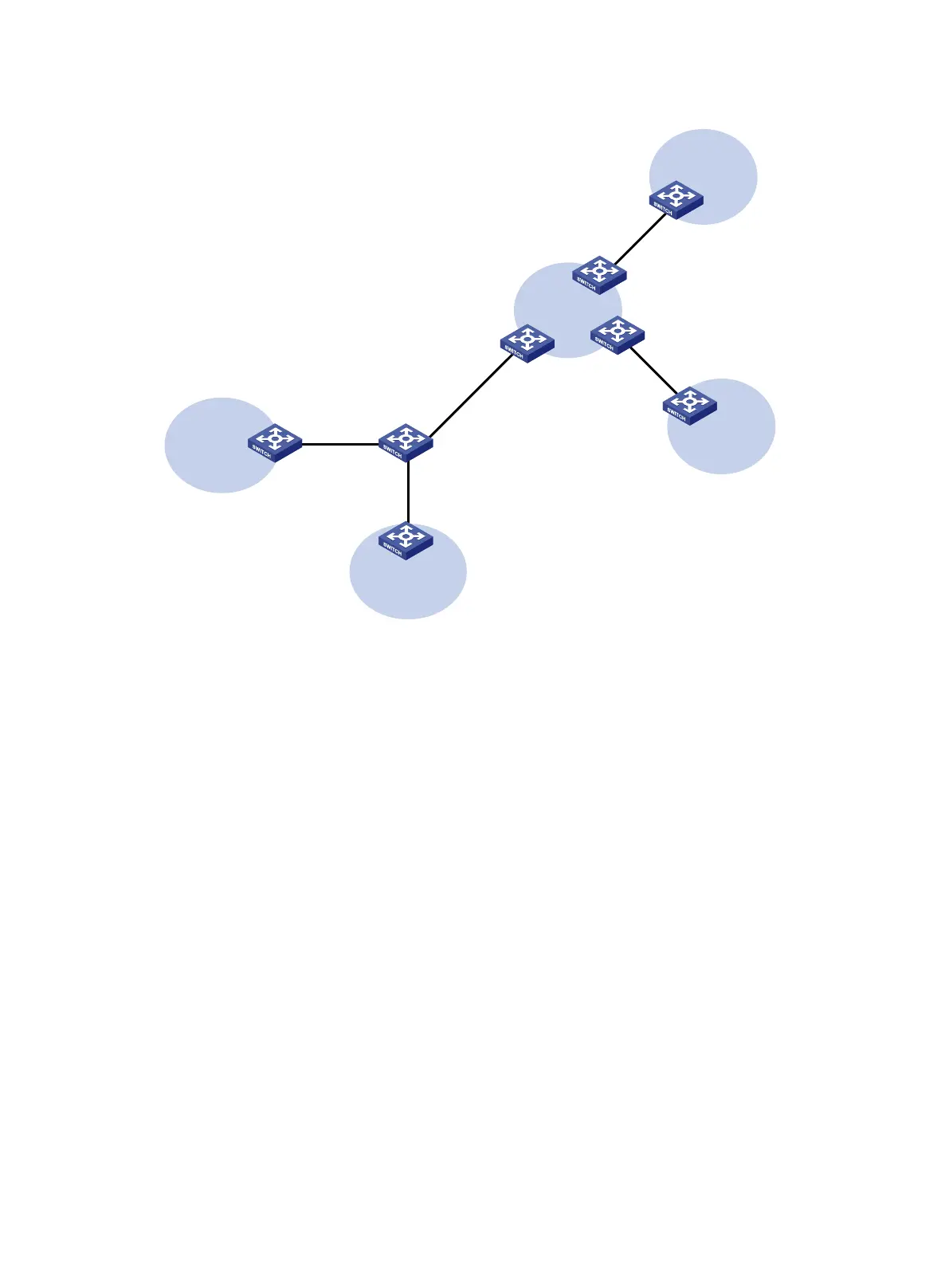
Figure 111 Network diagram
Configuration procedure
1. Create VPN instances on the MCE and PE 1, and bind the VPN instances to VLAN interfaces.
For the configuration procedure, see "Configure the VPN instances on the MCE and PE 1:."
2. Configure routing between the MCE and VPN sites:
# Enable an OSPF process on the devices in the two VPNs, and advertise the subnets. (Details
not shown.)
# Configure OSPF on the MCE, and bind OSPF process 10 to VPN instance vpn1 to learn the
routes of VPN 1.
<MCE> system-view
[MCE] ospf 10 router-id 10.10.10.1 vpn-instance vpn1
[MCE-ospf-10] area 0
[MCE-ospf-10-area-0.0.0.0] network 10.214.10.0 0.0.0.255
[MCE-ospf-10-area-0.0.0.0] quit
[MCE-ospf-10] quit
# Display the routing table of VPN 1 on the MCE.
[MCE] display ip routing-table vpn-instance vpn1
Destinations : 13 Routes : 13
Destination/Mask Proto Pre Cost NextHop Interface
0.0.0.0/32 Direct 0 0 127.0.0.1 InLoop0
10.214.10.0/24 Direct 0 0 10.214.10.3 Vlan10
10.214.10.0/32 Direct 0 0 10.214.10.3 Vlan10
10.214.10.3/32 Direct 0 0 127.0.0.1 InLoop0
CE
2
VPN 1
Site 2
CE
1
VPN
2
Site
1
PE
1
PE
3
PE
2
VPN 2
192.168.
10.0
/24
VR
2
VPN
1
192.
168
.0
.0
/
24
VR 1
MCE
GE1/0/1
Vlan
-int
10
10.214
.10.3
/
24
GE1/0/2
Vlan
-int20
10.214
.20.3
/24
GE
1/
0
/1
Vlan
-int30:
30.1.1.2/24
Vlan-int40: 40.1.1.2/24
GE1/0/3
Vlan-int30: 30.1.1.1/24
Vlan-int
40:
40
.1
.
1.
1/
24

 Loading...


