EDGE Pro Ti CNC Instruction Manual 807660 133
Maintenance and Diagnostics
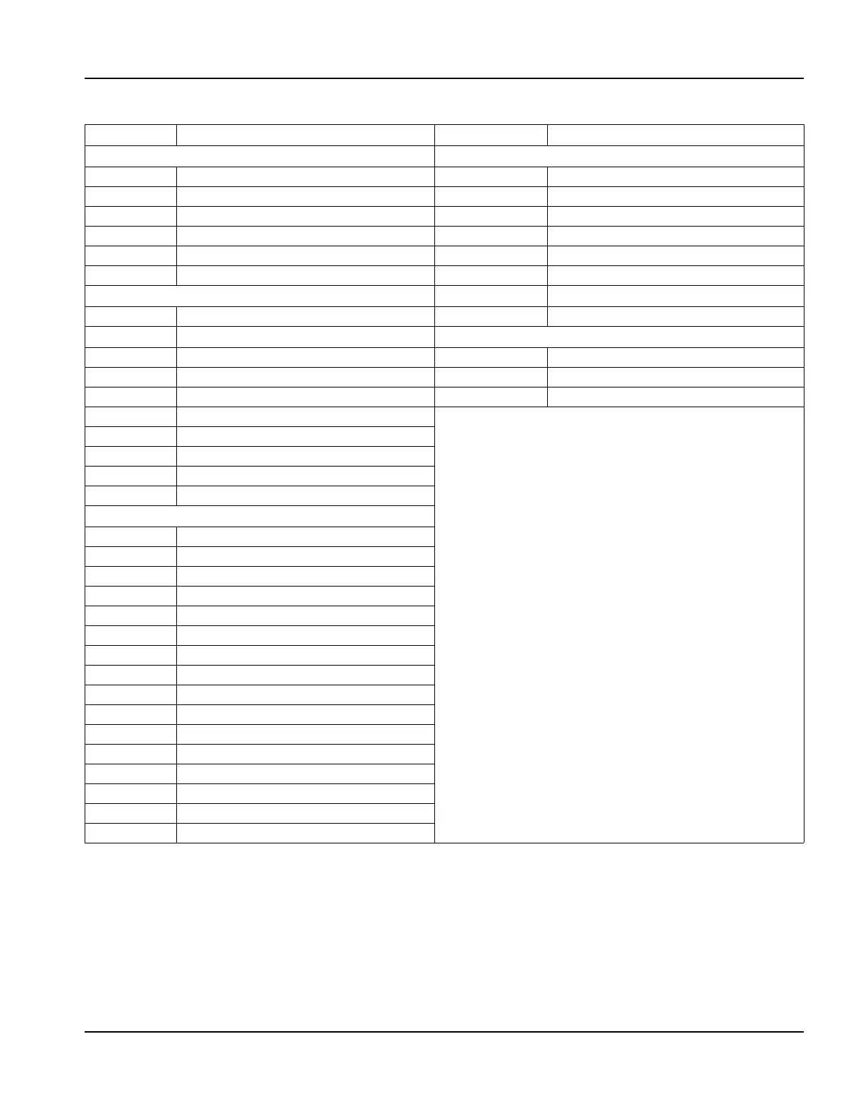
Relay I/O board (141278)
Table 34 Pinout for J1 to J6
Pin no. Signal Pin no. Signal
J1 To surge board J5 To 60 V AC/DC power supply
1 E-Stop active A 1 60 V inhibit B
2 E-Stop active B 2 60 V inhibit A
3 60 V inhibit A 3 Ground
4 60 V inhibit AB 4 AC/DC power good
5 Spare Out A 5 60 V inhibit A
6 Spare Out B 6 60 V inhibit B
J2 Lifter interface
7 XP 5 V standby
1 +12 V 8 Not connected
2 Lower limit switch
J6 Arc voltage utility
3 Upper limit switch 1 Ground
4 Breakaway switch 2 Arc voltage
5 Field ground 3 Not connected
6 Field ground
7 Plate contact -12 V
8 Plate contact sense
9 Plate contact common
10 Not connected
J3 plasma interface
1+12 V
2+12 V
3 Plasma start output
4 Plasma start output
5 Hold ignition output +
6 Hold ignition output
7Transfer input+
8Transfer input-
9 Field ground
10 Field ground
11 Field ground
12 Field ground
13 Field ground
14 Electrode arc voltage-
15 Electrode arc voltage+
16 Not connected