EDGE Pro Ti CNC Instruction Manual 807660 45
Installation
Mounting the THC
11. The metal braided shield on the torch lead must be connected firmly to the ignition/gas connect console
and to the torch. It is recommended to be electrically insulated from any metal and from any contact with
the floor or building. The torch lead can be run in a plastic cable tray or track, or covered with a plastic or
leather sheath.
12. The torch holder and the torch breakaway mechanism – the part mounted to the lifter, not the part
mounted to the torch – must be connected to the stationary part of the lifter with copper braid at least 12.7
mm (0.5 inches) wide. A separate cable must run from the lifter to the gantry ground bus bar. The valve
assembly should also have a separate ground connection to the gantry ground bus bar.
13. If the gantry runs on rails that are not welded to the table, then each rail must be connected with a ground
cable from the end of the rail to the table. The rail ground cables connect directly to the table and do not
need to connect to the table ground bus bar.
14. If you are installing a voltage divider board, mount it as closely as possible to where the arc voltage is
sampled. One recommended location is inside the plasma system enclosure. If a Hypertherm voltage
divider board is used, the output signal is isolated from all other circuits. The processed signal should be
run in twisted shielded cable (Belden 1800F or equivalent). Use a cable with a braided shield, not a foil
shield. Connect the shield to the chassis of the plasma system and leave it unconnected at the other end.
15. All other signals (analog, digital, serial, and encoder) should run in twisted pairs inside a shielded cable.
Connectors on these cables should have a metal housing. The shield, not the drain, should be connected
to the metal housing of the connector at each end of the cable. Never run the shield or the drain through
the connector on any of the pins.
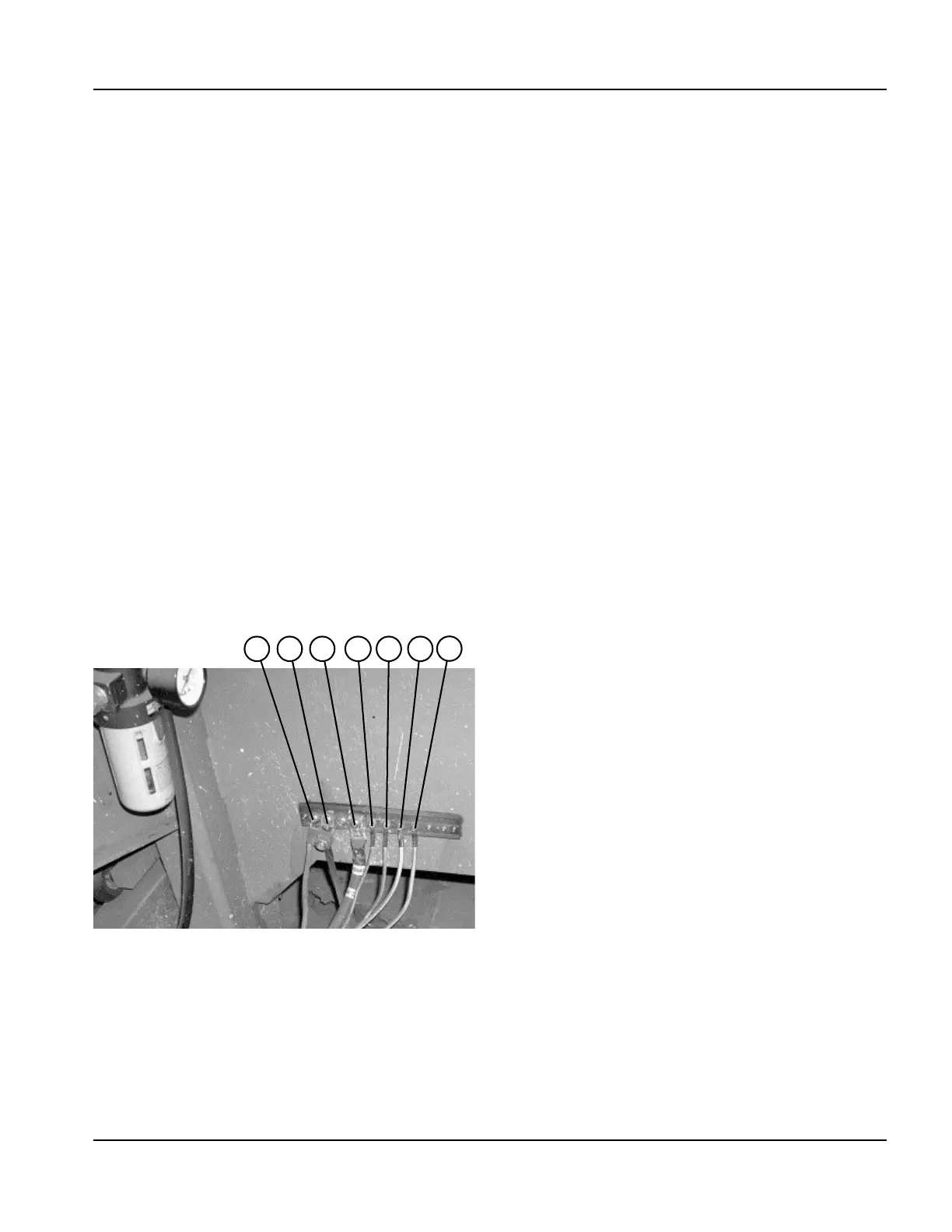
The following picture shows an example of a cutting table ground bus. The components shown here may differ from your
system.
1 Gantry ground bus
2 Ground rod
3 Plasma system lead (+)
4 RHF console (if applicable, not on all systems)
5 CNC enclosure
6 Torch holder
7 Plasma system chassis
1 2 3
4
5 6 7