EDGE Pro Ti CNC Instruction Manual 807660 47
Installation
Mounting the THC
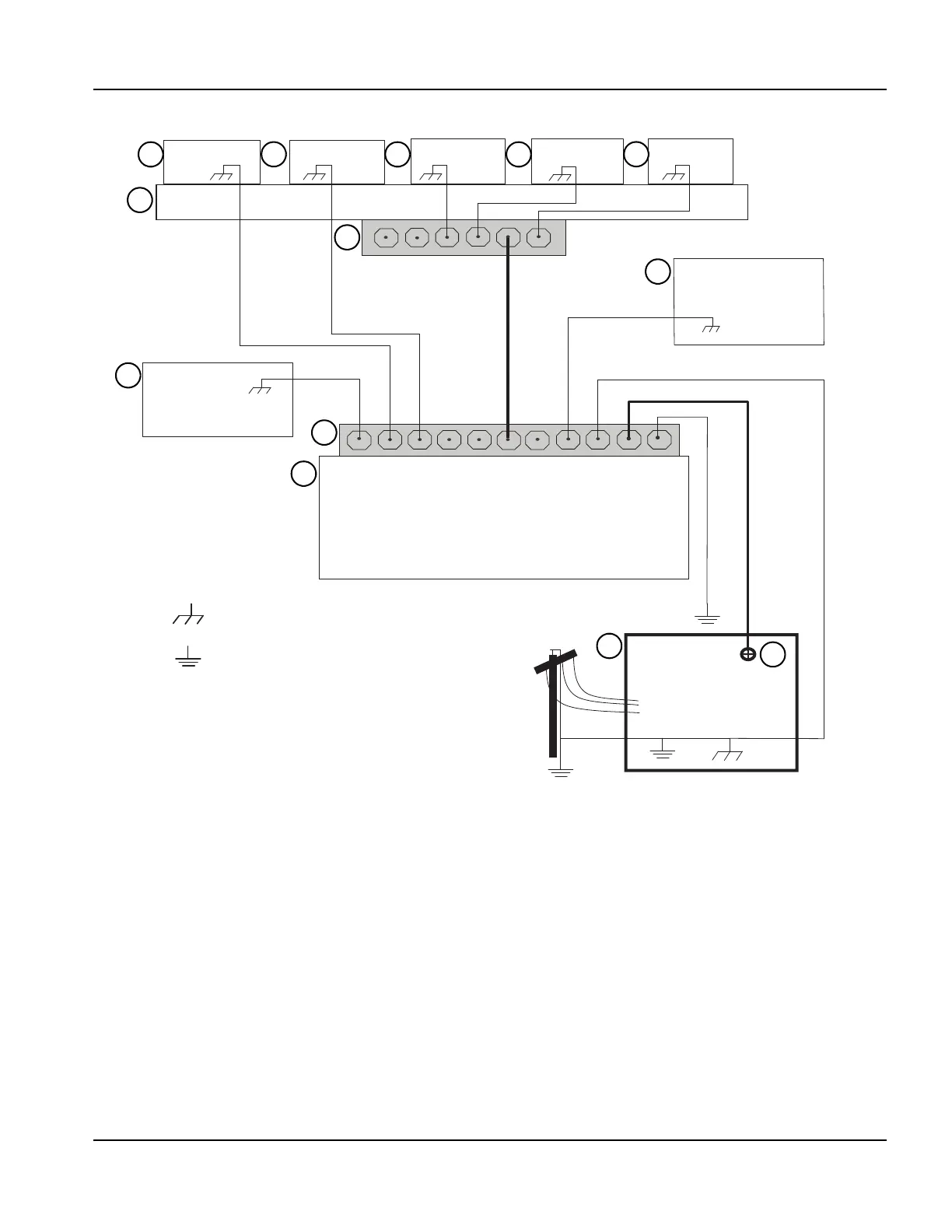
Example grounding diagram
Note: This example is based on practices in North America. Other regions can have different local or national
electrical codes. Hypertherm recommends that you consult your local and national electrical codes to make sure
that the grounding and shielding practices that you use satisfy the requirements for your location.
Chassis and RFI ground
AC earth ground (PE)
1
2
3
4
5
6
7
8 9
10
11
12
13
1 Cutting table
2 Gantry
3 Plasma system
4 Table ground bus bar
5 Gantry ground bus bar
6 Torch height control lifter (ArcGlide, Sensor THC,
Sensor PHC, or other)
7 RHF console (not on all systems). Connect to
table ground bus bar.
8, 9 System-specific component such as metering
console, gas console, or selection console
10 CNC chassis
11 Torch height control module
(ArcGlide, Command THC)
12 System-specific component such as a cooler or
chiller
13 DC power ground