84 EDGE Pro Ti CNC Instruction Manual 807660
Installation
Plasma connection
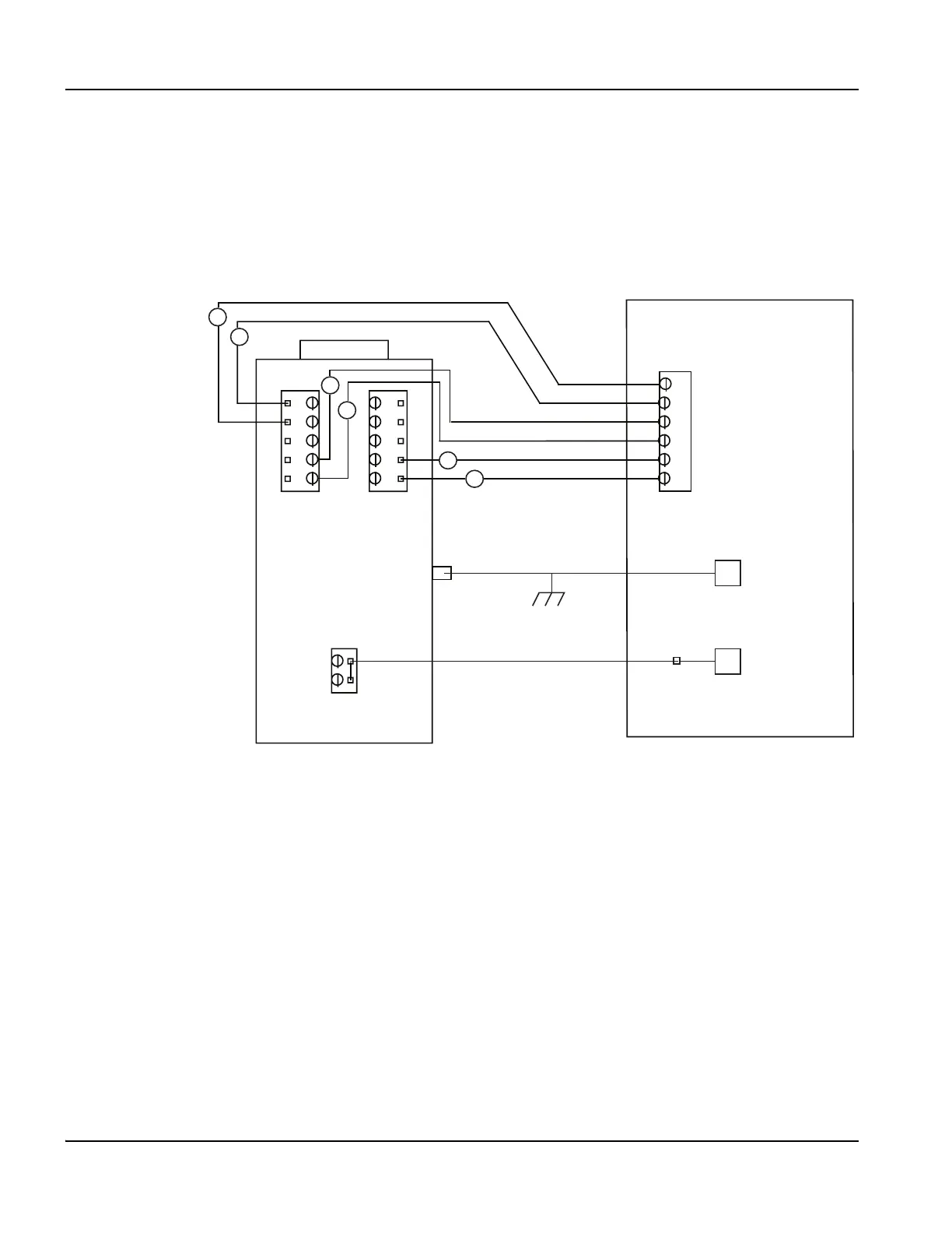
Figure 45 provides a conceptual representation of how the plasma interface is wired to the control board in the plasma
system. Refer to Table 16 on page 77 for detailed information about signal types and ratings.
To make the electrical connections for these signals within your plasma system, refer to the manual for your plasma
system for more detailed information.
Figure 45 Wiring between the plasma interface and control boards
For more information about the board within this assembly, see “Plasma interface board (141267)” on page 128.
Control board in the
plasma system
Work (+)
Electrode (-)
To the star ground on the work
table (+)
Arc voltage (-)
Plasma interface board
1
1
Start -
2
Start +
3
Hold +
4
Hold -
5
Transfer -
6
Transfer +
J3
J1
J2
P1