196 Powermax125 Service Manual 808070
9 – Power Supply Component Replacement
7. Lift up the end of the power supply base, and carefully slide the rear panel against the base until the base sits
securely on the panel. Tighten the 3 supplied mounting screws to 23 kg-cm (20 inch-pounds).
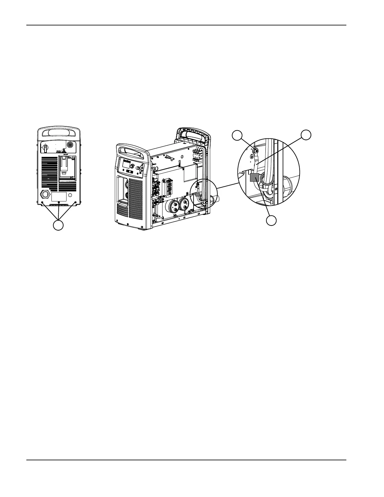
8. Secure the ground wire to the heatsink by tightening the ground screw to 23 kg-cm (20 inch-pounds).
The power board is removed in Figure 66 to show the ground wire connection on the
heatsink.
Figure 66
9. Complete the following procedures:
a. See Connect the gas tube on page 189.
b. See Install the end panel bracket on page 175.
c. See Install the component barrier on page 173.
d. See Install the power supply cover on page 172.
e. Reconnect the power and gas supply.
1 Rear panel mounting screws
2 Ferrite core (CE models)
3 Ground wire
4 Screw