12. Coordinate System Data Editing of the SCARA Axis
: 1 axis – 4 axis of the X-SEL-KX and PX/QX controller
174
159
14.1. Editing of work coordinate system data
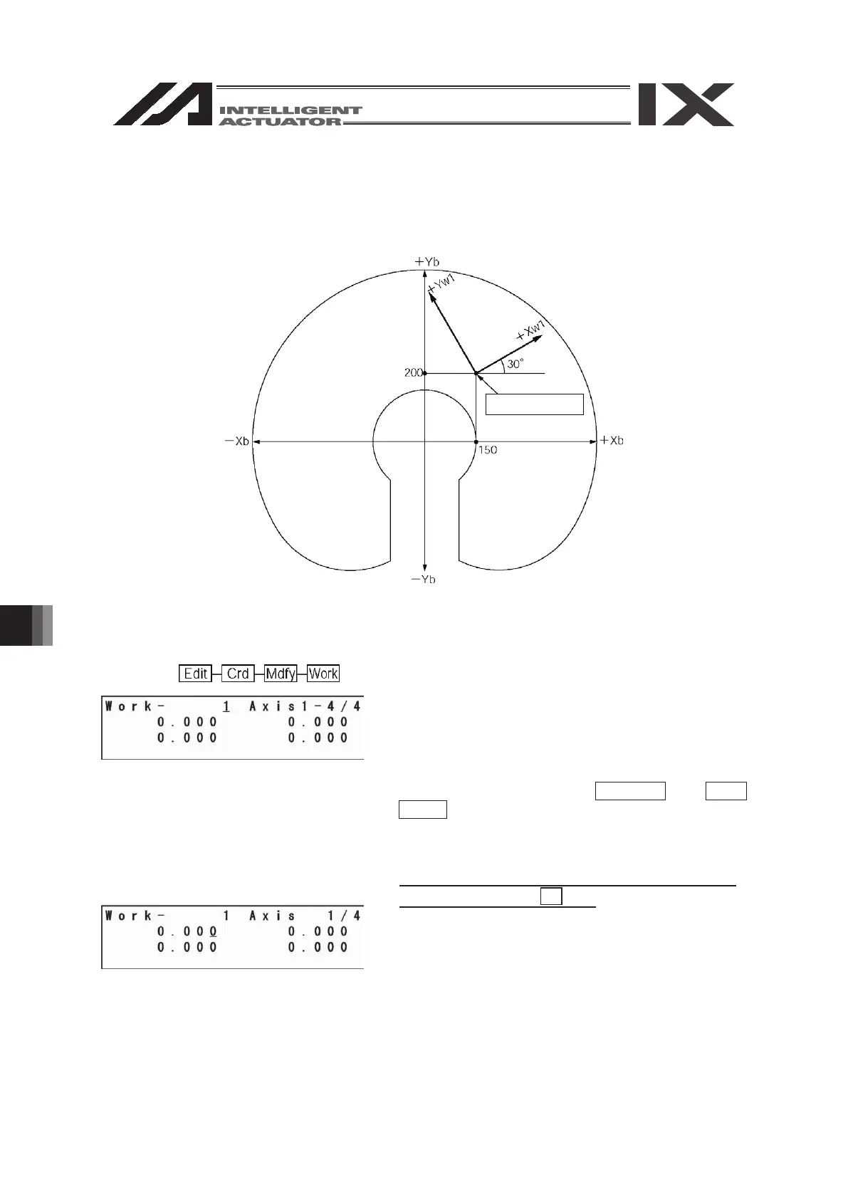
As an input example of the work coordinate system data, a coordinate system as shown below is
set for the work coordinate system No. 1.
(Motion range at the arm length 500-type stroke)
The offset values from the work coordinate system No. 1 are Xofw1 = 150, Yofw1 = 200, Zofw1 =
0 and Rofw1 = 30.
Mode flow:
This is the work coordinate system No. selection
screen.
The cursor is located at the work coordinate system
No.
To select the work coordinate system No., enter the
No. with the 10 key or the PAGE UP and PAGE
DOWN keys, and confirm it with the return key.
This example indicates the setting of the work
coordinate system No. 1.
Press the return key as it is.
The cursor is located at the X-axis offset value data.
Enter 150 and press the return key.
Origin of work
coordinate system No. 1
12.1.