28
8.2. X-SEL KX Controller
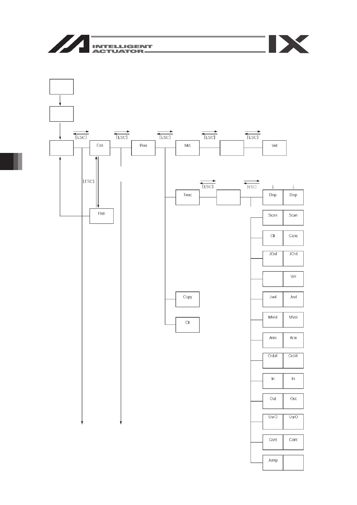
Power ON
Communications
established
Mode
selection
(Edit)
Function key Function key Function key
Select position No.
and press return
(Position) (Manual input)
Position data
input
* After writing data with [WRT],
move to the next position
* When escaping the mode
with [ESC], check whether to
write to Flash ROM.
“Yes” or “No”
(Write to
Flash ROM)
Function key
Select position No.
and press return
(Teach)
Position data
input
* After writing data with [WRT],
move to the next position
(Clear)
(Copy/movement)
Function key
(Velocity input)
Cursor
position No.
Each-axis cursor
position data
(Display
change)
(Data import)
(Clear)
(Jog
coordinate
system)
(Movement
velocity)
(Input
monitor)
(Arm system
change)
(Coordinate
system No.
change)
(Output
monitor)
(User-specified
output port
monitor)
(Jog velocity)
(Continuous
movement)
(Jump
movement)
(Display
change)
(Data import)
(Cancel)
(Jog
coordinate
system)
(Movement
velocity)
(Input
monitor)
(Arm system
change)
(Coordinate
system No.
change)
(Velocity data)
(Output
monitor)
(User-specified
output port
monitor)
(Jog velocity)
(Continuous
movement)
Cont
(Continuous
movement)
6.2.