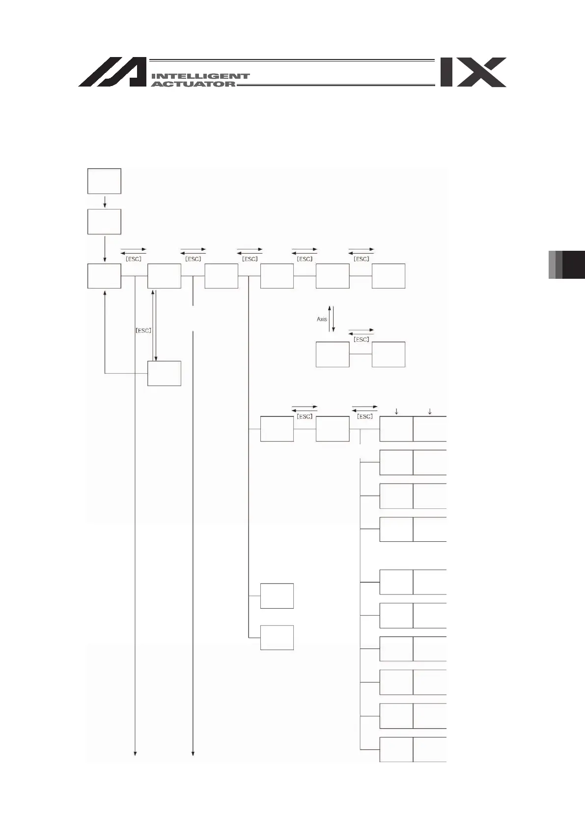
6. Mode Transition Diagram
23
Power ON
Communications
established
Mode
selection
Function key Function key Function key
Select position No. and
press return
Posi
(Position)
Mdi
(Manual input)
Position data
input
* After writing data with [WRT],
move to the next position
* When escaping the mode
with [ESC], check whether to
write to Flash ROM.
“Yes” or “No”
Flash
(Write to
Flash ROM)
Function key
Teac
(Teach)
Clr
(Clear)
Copy
(Copy/Move)
Function key
Vel
(Velocity
input)
Cursor
position No.
Each-axis cursor
position data
DiSP
(Di
splay
change)
Scan
(Data import)
Clr
(Clear)
DiSP
(Display
change)
Scan
(Data import)
Canc
(Cancel)
In
(Input
monitor)
Vel
(Velocity data)
Out
(Output
monitor)
JVel
(Jog velocity)
Cont
(Continuous
movement)
In
(Input
monitor)
Out
(Output
monitor)
JVel
(Jog velocity)
Cont
(Continuous
movement)
Position data
input
* After writing data with [WRT],
move to the next position
Axis
(Axis No.
display
change)
Axis
(Axis No.
display
change)
The above are effective only for the
5-axis/6-axis spec. controllers.
UsrO
(User-specified
output port
monitor)
(User-specified
output port
monitor)
Edit
Cont
(Continuous
movement)
Function key Function key
Position data
input
Vel
(Velocity
input)
1-axis - 4-axis
5-axis, 6-axis
6. Mode Transition Diagram
 Loading...


