12. Coordinate System Data Editing of the SCARA Axis
: 1 axis – 4 axis of the X-SEL-KX and PX/QX controller
177
162
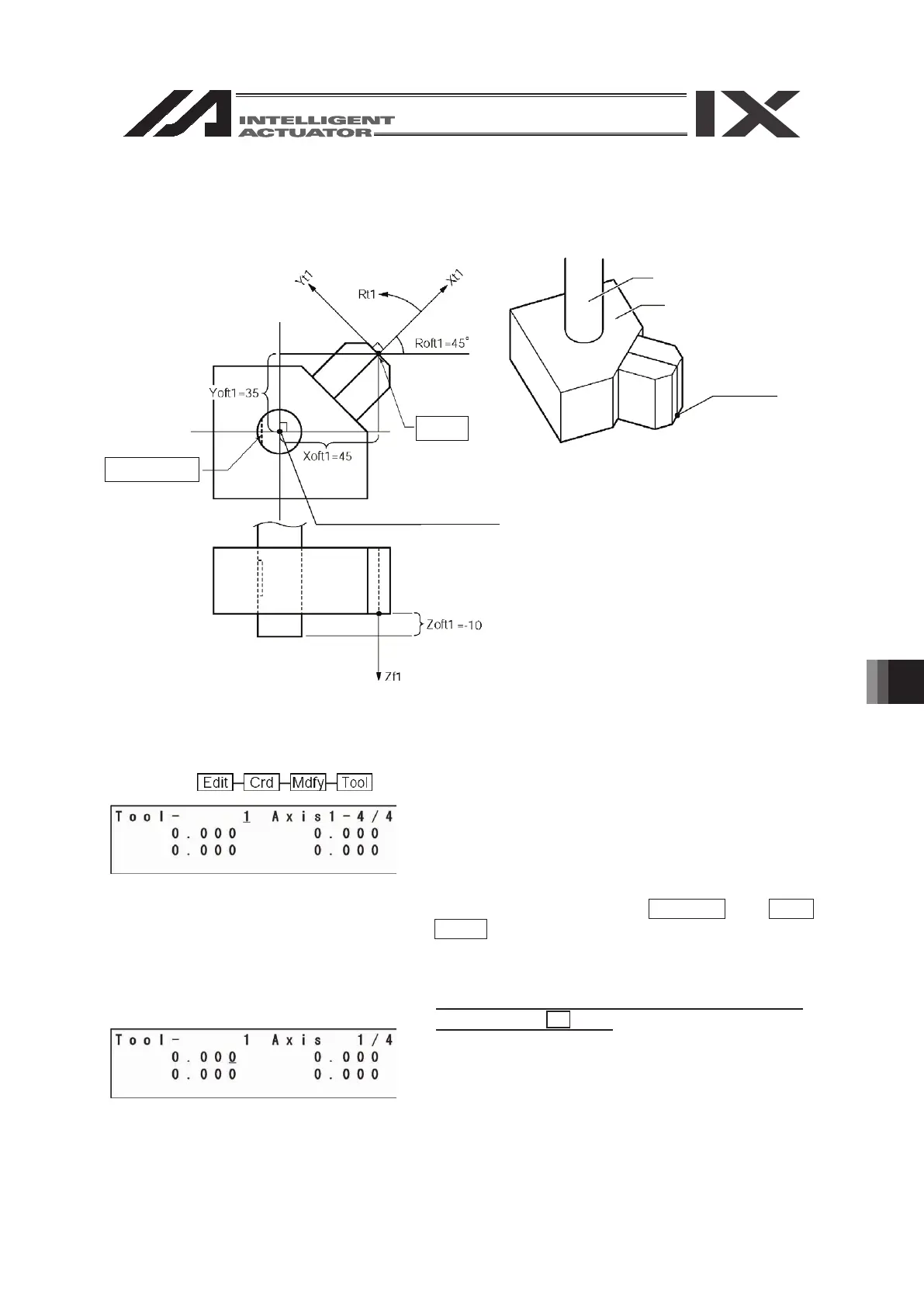
14.2. Editing of tool coordinate system data
As an input example of the tool coordinate system data, a tool as shown below is set for the tool
coordinate system No. 1.
The offset values from the tool coordinate system No. 1 become Xoft1 = 45, Yoft1 = 35, Zoft1 =
-10 and Roft1 = 45.
Mode flow:
This is the tool coordinate system No. selection
screen.
The cursor is located at the tool coordinate system
No.
To select the tool coordinate system No., enter the
No. with the 10 key or the PAGE UP and PAGE
DOWN keys, and confirm it with the return key.
This example indicates the setting of the tool
coordinate system No. 1.
Press the return key as it is.
The cursor is located at the X-axis offset value data.
Enter 45 and press the return key.
D-cut surface
Tool tip
Tool mounting surface center
R-axis
Tool
Tool tip
12.2.
 Loading...


