5. How to Save Data
20
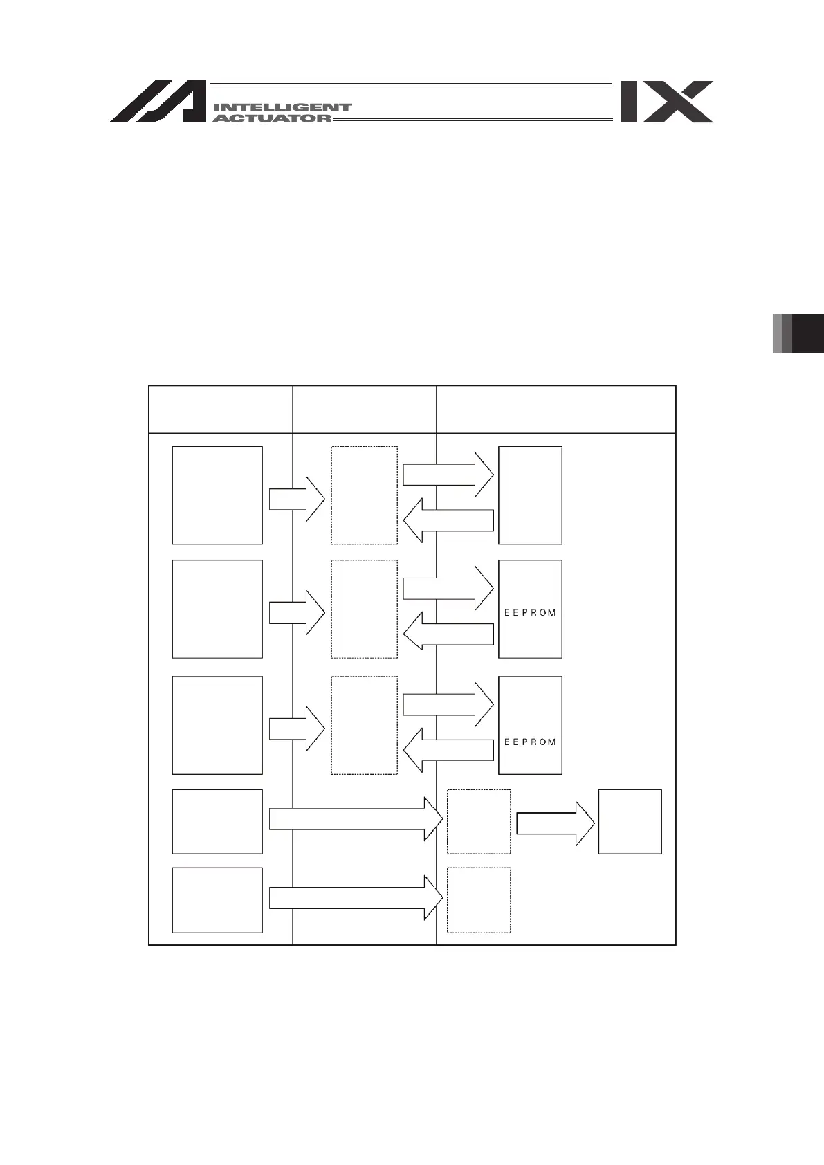
7. How to Save Data
Since the Controller adopts flash memory, there is a storage area by battery backup and a
storage area by flash memory according to the data to be stored.
In addition, even if data is transferred from the PC software or Teaching Pendant, the data is only
to be written in memory as shown in the chart below and the data is erased by power-off or
controller reset.
To ensure data storage, write the data you want to store in flash memory.
7.1. Set-up at Shipment with System Memory Backup Battery
(Other parameter No. 20=2 (System memory backup battery equipped))
* Encoder parameters are not stored within the controller but in the EEPROM of the actuator’s
encoder itself. They are read into the controller at power-on or software-reset time.
Edit data with PC or
Teaching Pendant
Save the data during the
power is on and delete
the data by reset
Save data even after the power OFF
Program
parameter
(content 1)
Symbol
Slave card
parameter
(content 2)
Transmit
Transmit
Transmit
Transmit
Transmit
* Encoder
parameter
Position
SEL global data
(content 3)
Error list
Memory
Memory
Memory
Flash write
Reset read
Transmit
Reset read
Transmit
Reset read
Flash
memory
* Encoder
Battery
backup
memory
Flash write
Battery
backup
memory
Flash
memory
5.
19
▪ Such jog actions with the JOG button are also valid for any not-homed axes. However,
coordinate values in this case have no meaning. Therefore, be extremely careful about
interference with the stroke end.
▪ If jog operation is performed to the axis in action under the operation-button-acceptable
condition, the operation of the applicable axis is aborted when the JOG operation button is
turned OFF. (The next operation starts, if any.)
18. Deadman switch (*Option)
The Deadman switch has three-level conditions. The ON/OFF in each level is as shown
below.
1st level Switch OFF Condition in which the switch is released or a switch pressing
force is too weak
2nd level Switch ON Condition in which the switch is pressed by an appropriate
force
3rd level Switch OFF Condition in which the switch is pressed by a strong force
In the switch ON condition, servo ON is possible.
In the switch OFF condition, the driver power is cut off and the servo is turned OFF.
Even
in the switch OFF condition, operation is possible in the mode not requiring servo ON
(such as the edit
mode).
◎Some controllers such as the X-SEL-K controller display the message shown below when
the power is turned on.
If you press the ESC key, the mode selection screen will be displayed and operation will
become possible in the mode not requiring servo ON even in the switch OFF condition.
◎When the switch is OFF, the panel window 7-segment LED of the X-SEL-K or KX controller
displays “dsf.”
The panel window 7-segment LED of the X-SEL-P/Q or PX/QX, R/S, RX/SX, RXD/SXD
controller displays “enb.”
▪ The Deadman switch is valid when the controller’s mode switch is on the MANU side.
▪ The driver power cannot be cut off regardless of the switch condition when the controller’s
mode switch is on the AUTO side.
Caution
Caution