236
(5) Set the preset home value to uniform the coordinate values of the master and slave axes.
① If the controller 7 segment display is “rdy” while the servo is OFF, read the displayed
current positions of the master and slave axes.
(If the error No. C74 real position soft limit over error occurs, reset the error. When “rdy” is
displayed, the displayed current positions can be read.)
Mode Transition:
* If the servo is turned ON at this stage, error No. D0A driver overload error, error No. C6B
deviation overflow error, error No. CA5 stop deviation overflow error, etc., occurs.
② Calculate the following:
Each-axis parameter No. 12 preset home value for slave axis [0.001 mm]
+ ((displayed current position value for master axis [mm] - displayed current position
value for slave axis [mm]) × 1000)
In this example:
-977 + ((-0.006-1.731) × 1000)) = -2714
③ Input the calculation result in ② above to the “each-axis parameter No. 12 preset home
value” for the slave axis.
After pressing the return key, press the WRT key to
transfer the data.
Move to the Flash ROM writing screen with the ESC
key.
Slave axis
237
Supplement
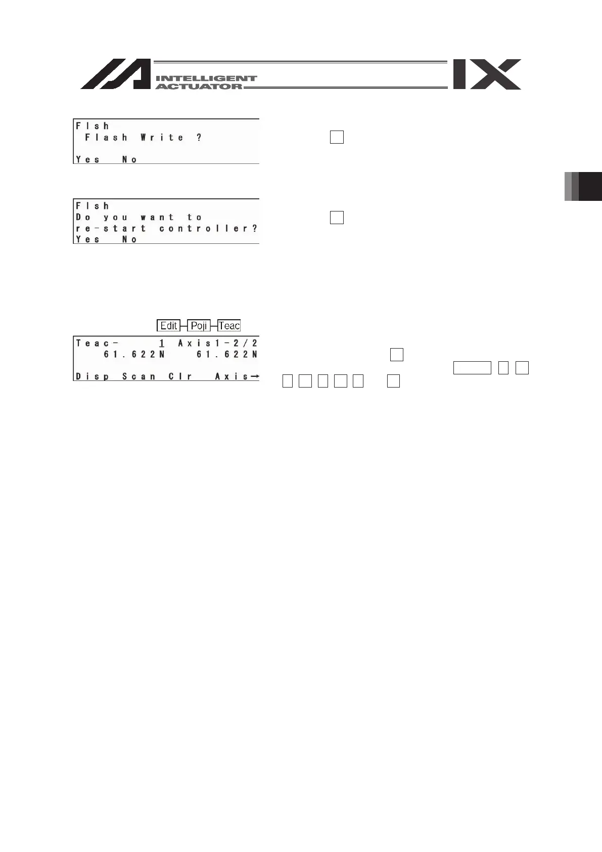
Write the data to Flash ROM.
Press the F1 (Yes) key.
Restart the controller.
Press the F1 (Yes) key.
(7) Display the current positions on the teaching screen.
After turning the servo ON, execute action check by jogging. (Master axis operation)
Mode Transition:
To switch the current position screen to the input
data screen, press the F3 (Disp) key.
To turn the servo ON/OFF, use the SERVO, 1-, 1+,
2-, 2+, 3-, 3+, 4- and 4+ keys.
If the error No. D0A driver overload error, error No. C6B deviation overflow error, error No. CA5
stop deviation overflow error, etc., occurs, check the following items:
▪ If the current position of the master axis is greatly different from that of the slave axis, setting
in (5) may be wrong.
▪ Confirm that there are no input errors or change omissions as for the parameters below.
“Each-axis parameter No. 65 synchro other axis No.”
“Each-axis parameter No. 83 ABS synchro slave axis coordinate initialization cancel”
▪ Confirm that slider actions are not restrained.
4. Standard Procedure Absolute Reset
In the case of “each-axis parameter No. 38 encoder ABS/INC type:” master axis = 1 and slave
axis = 0:
After “2. Location Adjustment of Synchro Axes Sliders,” execute a normal absolute reset only for
the master axis.
For the operating method, refer to the Teaching Pendant Instruction Manual.
Note: The synchro axis for which the standard procedure absolute reset has been executed does
not have the function of correcting the slider displacement during power OFF after the
servo is turned ON.
 Loading...


