New
40
7
DV MODE OPERATION
New2001
■ About the D-STAR system
In the D-STAR system, repeater linking via a 10 GHz band
backbone and internet network (gateway connection) capa-
bilities are available. This system provides you with much
wider coverage range during digital voice mode operation.
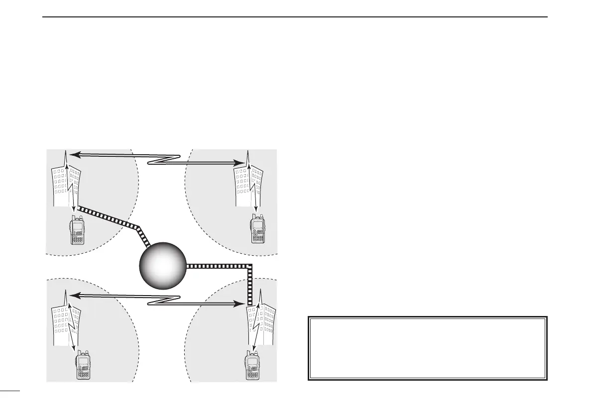
• D-STAR system outline
For current repeater operation, stations that are communi-
cating must both be in the same repeater’s operating area.
However, in the D-STAR system as in the illustration at left,
the repeaters can be linked via the system repeaters (with
a 10 GHz signal). Thus stations A and B can communicate
even though they are in different repeater operating areas.
Also, the D-STAR system repeaters are connectable through
the internet— gateway connection capability.
For example, when station B uses the gateway connection
station B can communicate with the station C!
By using the gateway connection, long distance communica-
tion like DX operation may be possible with 144 or 430 MHz
digital voice!
In the D-STAR system, an independent repeater’s operating
area is called an Area and a group that of linked repeaters
via a 10 GHz backbone is called a Zone.
About time-out timer function
The IC-E92D has a time-out timer function for digital re-
peater operation. The timer limits a continuous transmis-
sion for approx. 10 min. Warning beeps will sound before
30 sec. (approx.) and just before the timer functioning.
Station
A
Station C
Station D
Repeater A
Repeater D
430 MHz
430 MHz
Repeater C
10 GHz
Station
B
Repeater B
10 GHz
430 MHz
430 MHz
Internet
network
Internet
network