- 115 -
IS810N-INT Series Servo System User Manual (Brief)Chapter 4 Wiring
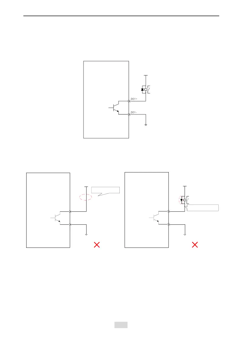
2) DO circuit
DO1–DO2 interface circuits are the same. The following takes DO1 interface circuit as an
example.
a) When the host controller provides relay input:
NOTE
When the host controller provides relay input, a ywheel diode must be installed; otherwise,
the DO ports may be damaged.
Servo drive
External 0 V
No relay is connected
External 5-24 VDC
继电器
Servo drive
External 0 V
External 5-24 VDC
Incorrect polarity of
flywheel diode
Relay
Servo drive
External 5-24 VDC
Relay
External 0 V
External 0 V
External 0 V
External 0 V
 Loading...