IS810N-INT Series Servo System User Manual (Brief) Chapter 6 Commissioning Software
- 170 -
a. Click
Auto
to automatically calculate the Y range value of the current curve.
b. Grid size: Change the Y-axis range by select a value corresponding to a
grid. The middle position is an average of the current range values, that is,
(YMax – Ymin)/2.
c. Up arrow: The waveform moves up one cell at a time.
d. Down arrow: The waveform moves down one cell at a time.
Sampling parameter settings
1> Sampling interval: Set a sampling interval coefcient in a valid range of 1 to 100.
Sampling interval = Sampling coefcient * 2 ms.
2> Time axis: Set a time length that the X-axis indicates in ms.
Control buttons
1> Continuous sampling: Start or stop continuous sampling.
•
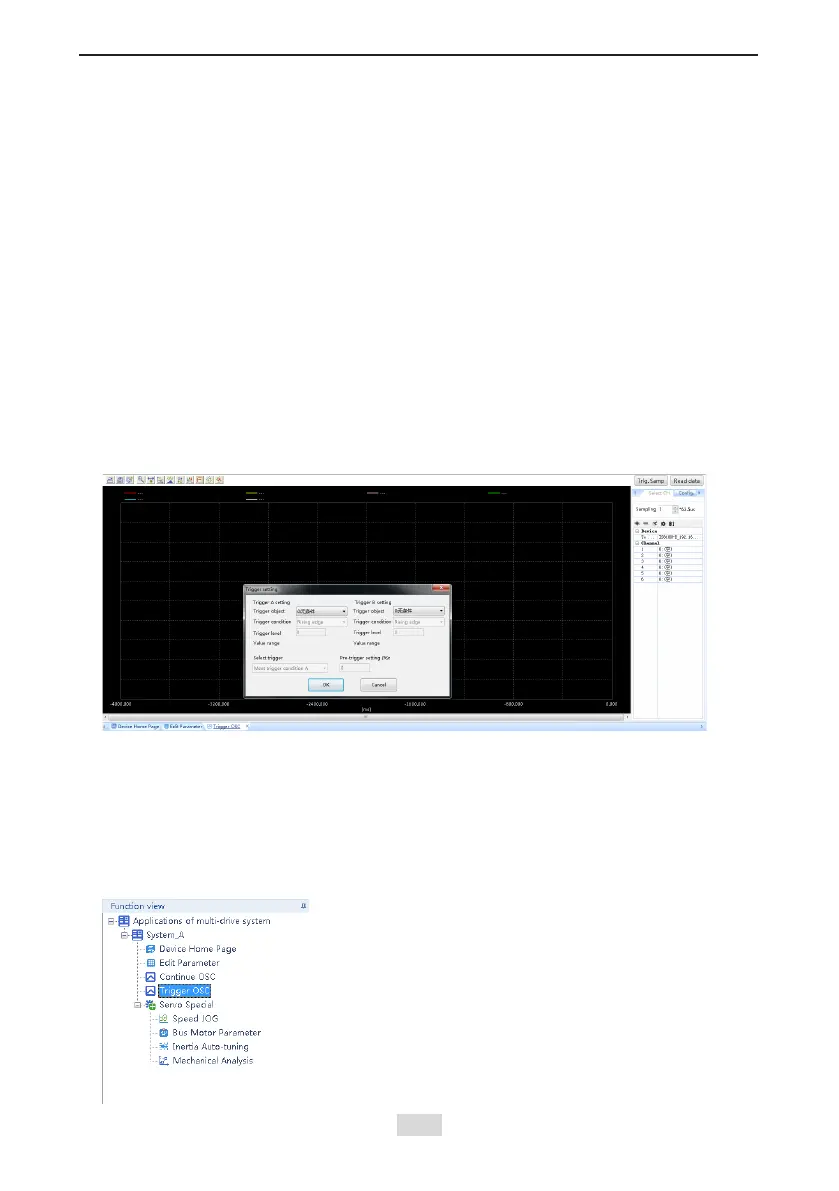
Trigger OSC
Choose
Function view
>
Trigger OSC
and double-click.
Functional Description:
The basic operations are the same as those for the continuous oscilloscope. After the
trigger parameters are set, a valid data segment can be read and displayed.
Control buttonsv
1> Single-time sampling: Start or stop single-time sampling.
2> Trigger setting: Display a dialog box that is used to set triggering parameters.
3> Bit channel conguration: Support conguring 8-bit channel display.
•
Servo Special
Choose
Function view
>
Servo Special
, double-click, and you can use the following
special functions for the servo:
 Loading...