- 93 -
IS810N-INT Series Servo System User Manual (Brief)Chapter 4 Wiring
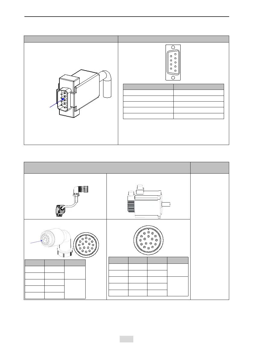
Table 4-4 Connectors of IS810N series 20-bit encoder cables on servo drive side
Connector Appearance Terminal Pin Layout
Pin No. Signal
1 PS+
2 PS-
7 +5 V
8 GND
Housing PE
Recommendation:
Plastic housing of plug on cable side: DB9P
(SZTDK), black housing
Core: DB9P soldering plug (SZTDK), blue rubber
Table 4-5 Connectors of IS810N series 20-bit encoder cables
(MIL-DTL-5015 series 3108E20-29S military spec.)
Connector Appearance and Pin Layout
Frame Size of
Applicable Motor
Encoder cable
connector
Connect to
CN2 of the
drive
Encoder connection
socket
100
130
180
20-29 military spec.
A
B
M
C
L
N
T
P
D
K
R
S
E
J
F
G
H
Pin No. Signal
A PS+
Twisted-
pair
B PS-
G +5 V
H GND
J Shield
20-29 military spec.
A
M
B
L
C
N
P
T
K
D
S
R
J
E
H
G
F
Pin No. Signal Color
A PS+ Yellow
Twisted-
pair
B PS- Blue
G +5 V Red
H GND White
J Shield
Frame size of motor: indicates the width of the installation ange.
 Loading...