- 94 -
IS810N-INT Series Servo System User Manual (Brief) Chapter 4 Wiring
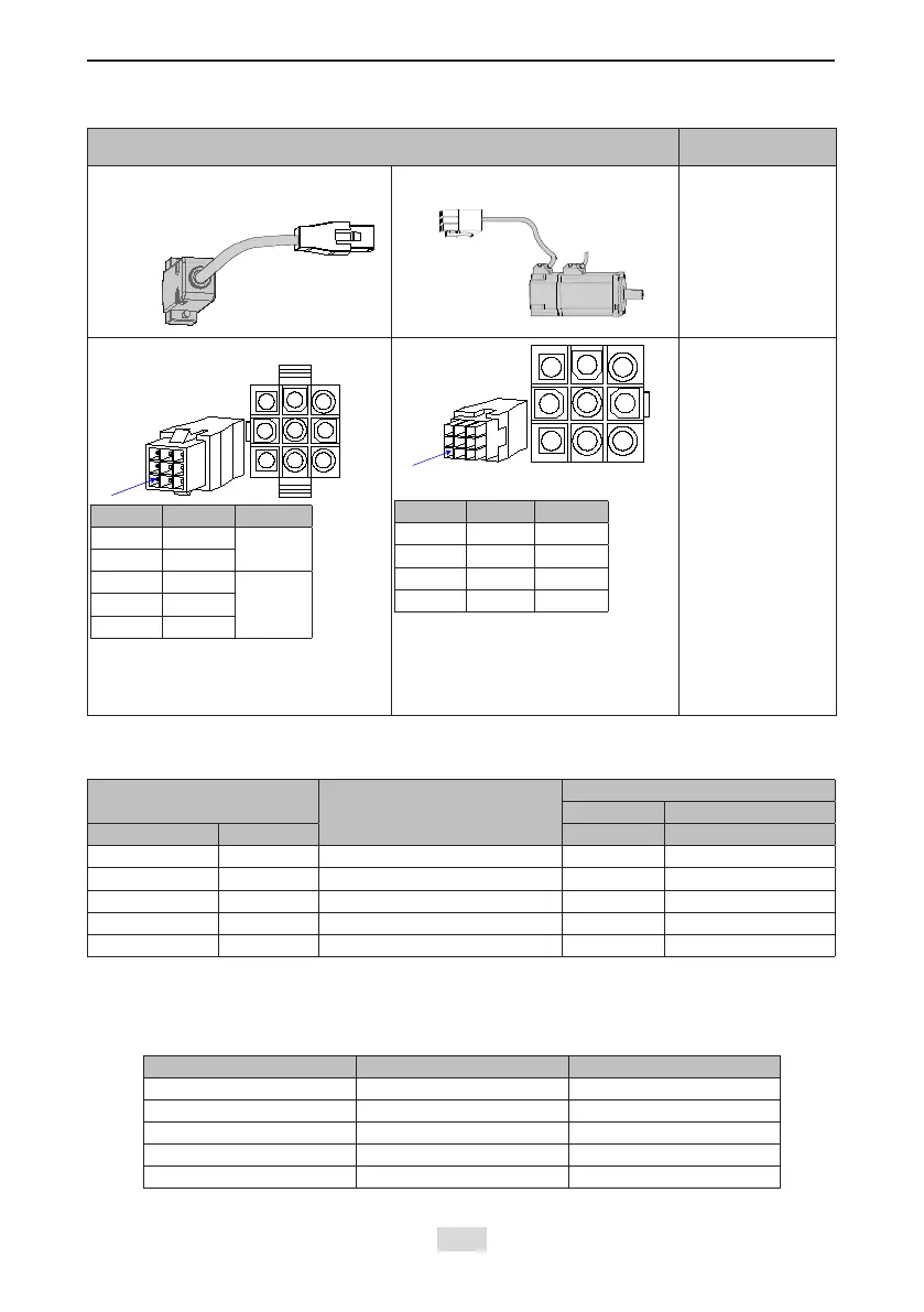
Table 4-6 Connectors of IS810N series 20-bit encoder cables (9-pin connector)
Connector Appearance and Pin Layout
Frame Size of
Applicable Motor
Encoder cable
connector
Connect to
CN2 of the
drive
40
60
80
9-pin connector
Pin No. Signal
3 PS+
Twisted-
pair
6 PS-
9 +5 V
8 GND
J Shield
Recommendation:
Plastic housing: AMP 172161-1;
Terminal: AMP 170359
Pin No. Signal Color
3 PS+ Yellow
6 PS- Blue
9 +5 V Red
8 GND White
Frame size of motor: indicates the width of the installation ange.
Table 4-7 Pin relationship of IS810N series 20-bit encoder cables
DB9 on Servo Drive Side
Function Description
Motor Side
9-pin 20-29 Aviation Plug
Signal Pin No. Pin No. Pin No.
PS+ 1 Serial communication signal + 3 A
PS- 2 Serial communication signal - 6 B
+5 V 7 Encoder +5 V power supply 9 G
GND 8 Encoder +5 V power ground 8 H
PE Housing Shield 7 J
It is recommended that the 22–26AWG cables and matching AMP170359-1 terminals be used for the
10B, 20B, 40B, and 75B series motors. If longer cables are required, cables with a larger diameter
should be used, as described in the following table.
Table 4-8 Recommended cable sizes
Cable Size Ω/km Allowed Cable Length (m)
26AWG (0.13 mm2) 143 10.0
25AWG (0.15mm2) 89.4 16.0
24AWG (0.21mm2) 79.6 18.0
23AWG (0.26mm2) 68.5 20.9
22AWG (0.32mm2) 54.3 26.4
If cables sized greater than 22AWG are required, contact Inovance.
 Loading...