CEAST 9340 - Instructions for Use and Maintenance 7510.000MN1r ed. 1 rev. 1 - Page 127
12. WIRING DIAGRAMS
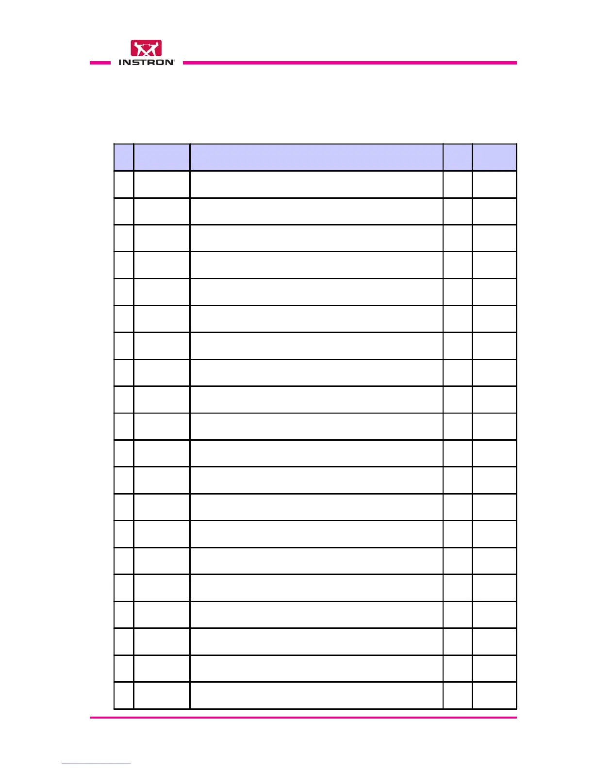
This section of the manual includes a complete copy of the wiring diagrams of “CEAST
9340" instrument as indicated in the list below:
Nr Diagram Nr Title Rev. Page
1 9340 Light Drop Tower 01 1 of 20
2 9340 Power Supply and Safety - 7510 AK 01 2 of 20
3 9340 Low Voltage - 7510 AK 01 3 of 20
4 9340 On Board - 7510 AK 01 4 of 20
5 9340 CPU Board - 7510 AK 01 5 of 20
6 9340 Power I/O Board - 7510 AK 01 6 of 20
7 9340 Other Options 01 7 of 20
8 9340 Thermostatic Cell 01 8 of 20
9 9340 Main Electrical Panel 01 9 of 20
10 9340 Thermostatic Cell Electrical Panel 01 10 of 20
11 9340 Terminal Block: X0 X0 - 1/1 01 11 of 20
12 9340 Terminal Block: X1 X1 - 1/1 01 12 of 20
13 9340 Terminal Block: X2 X2 - 1/1 01 13 of 20
14 9340 Terminal Block: X3 X3 - 1/1 01 14 of 20
15 9340 Terminal Block: X4 X4 - 1/1 01 15 of 20
16 9340 @Terminal Block: X5 @X5 - 1/1 01 16 of 20
17 9340 Lista Localizzazioni (Location List) 01 17 of 20
18 9340 Wire List 01 18 of 20
19 9340 Wire List 01 19 of 20
20 9340 Wire List 01 20 of 20