Page 92 - CEAST 9340 - Instructions for Use and Maintenance 7510.000MN1r ed. 1 rev. 1
8.7.4 REPLACEMENT OF THE INSTRUMENTED VICE FOR TENSILE-IMPACT
Authorized Personnel: Operator
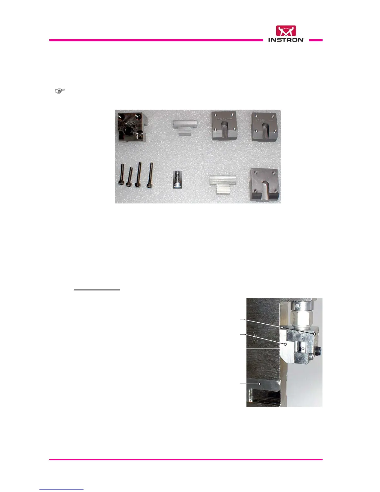
Fig. 1 - Example of clamping for rigid specimens according to ISO 8256 standard,
method A, type 1and 3 for tensile impact vice complete with 3 sets of gripping
adapters:
- A, B, C, E, F: for rigid specimens, thickness 3 mm;
- A, B, D, E, F: for rigid specimens, thickness 4 mm;
- A, E, F, G, H: for films only.
ABCD
FG
E
Note: for the identification codes of parts shown in fig. 1 below refer to the Appendix F
at the end of this document.
X
X
a) Push the sliding stop plate backward
as shown in the figure to the right side.
b) Remove the screws E (x4) and remove
the adapter C from downward.
c) Remove the plate B.
DISASSEMBLY
Sliding
stop plate
E
C
B
X
H