CEAST 9340 - Instructions for Use and Maintenance 7510.000MN1r ed. 1 rev. 1 - Page 91
X
X
a) Choose the correct range of the force sensor (2.2 kN or 0.45 kN) to be installed.
b) Push the sliding stop plate backward as shown in the Fig. 2A.
c) Screw the force sensor to the sensor cable (Fig. 2 A).
d) Put some drops of sealing compound (type Loctite 243, medium-strong) on the thread
of the force sensor (Fig. 2A).
e) Screw the force sensor by hand and in the mean time turn the signal cable togheter
with the sensor, avoiding to damage it. (Fig. 2B).
f) Tighten the force sensor using the open wrench (Fig. 2B).
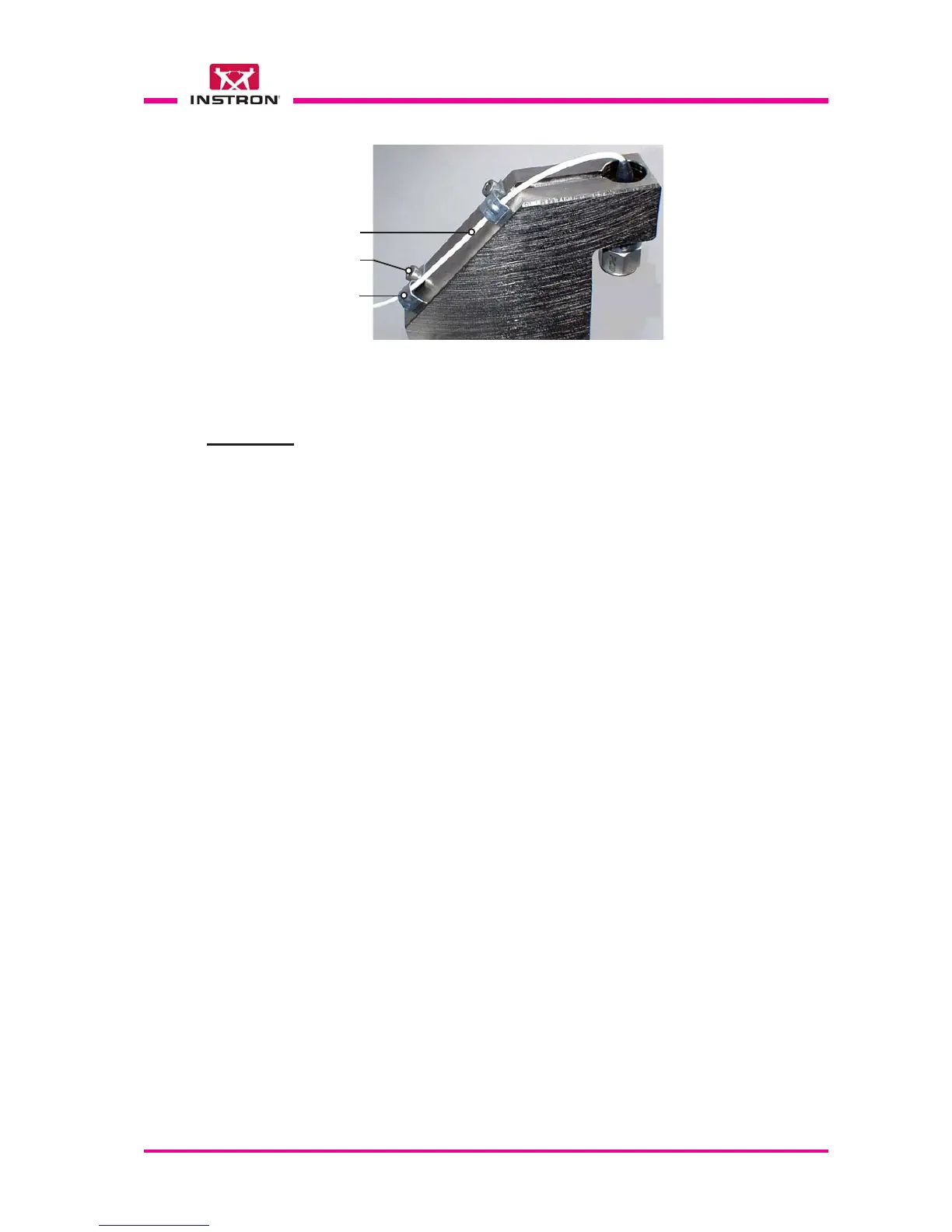
g) Pass the signal cable inside the clamps and fasten them with screws.
ASSEMBLY
X
X
X
Fig. 3 - Signal cable clamping
Signal cable
Screw (x2)
Clamp (x2)
X
X