Page 50 - CEAST 9340 - Instructions for Use and Maintenance 7510.000MN1r ed. 1 rev. 1
Vid. 1 - Main menu of the program
8.5.2 MAIN MENU
XXX mm XXX mm
XXX mm XXX mm
XXX mm
S:XXX.X°CS:XXX.X°C
S:XXX.X°CS:XXX.X°C
S:XXX.X°C
(d)XXX mm (d)XXX mm
(d)XXX mm (d)XXX mm
(d)XXX mm
R:XXX.X°CR:XXX.X°C
R:XXX.X°CR:XXX.X°C
R:XXX.X°C
SET TEMPERATURE SET TEMPERATURE
SET TEMPERATURE SET TEMPERATURE
SET TEMPERATURE
LOAD PARAMETERS LOAD PARAMETERS
LOAD PARAMETERS LOAD PARAMETERS
LOAD PARAMETERS
MODIFY PARAMETERS MODIFY PARAMETERS
MODIFY PARAMETERS MODIFY PARAMETERS
MODIFY PARAMETERS
SAVE PARAMETERS SAVE PARAMETERS
SAVE PARAMETERS SAVE PARAMETERS
SAVE PARAMETERS
RESULTS RESULTS
RESULTS RESULTS
RESULTS
UTILITY UTILITY
UTILITY UTILITY
UTILITY
SERVICE SERVICE
SERVICE SERVICE
SERVICE
>
1
5
4
1) Temperature set (Celsius degree) in the parameters file currently used.
2) Actual temperature (Celsius degree) measured from the temperature sensor in the en-
vironmental chamber.
When the conditioning is disabled (or when there is an error, e.g.: thermoregulator
cable detached) the temperature value is visualized as ????.?.
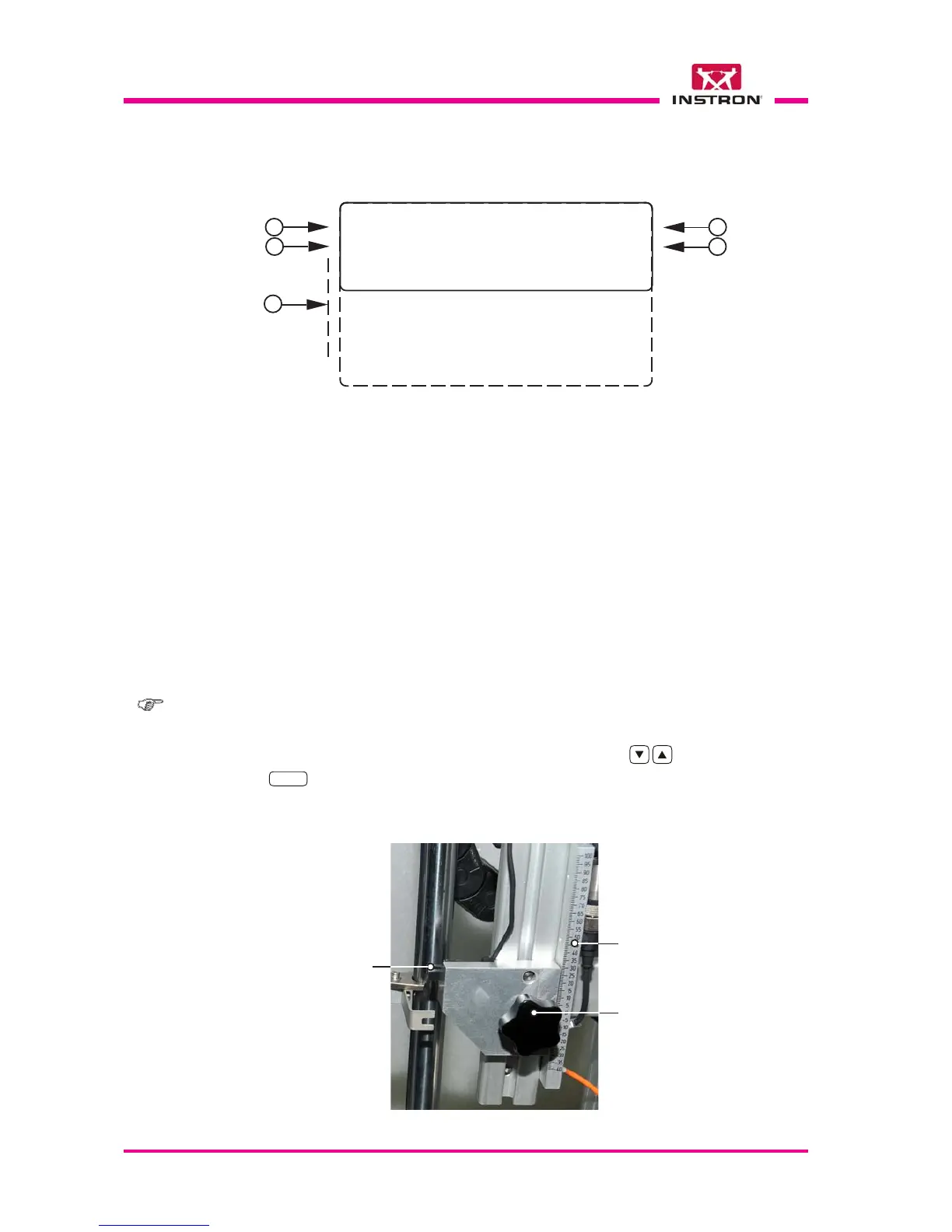
3) Position in millimeter to which the pointer of the optical detector (part of the striker velocity
measuring device) must be set on the rule located in the turret right side (see Fig. below).
The position is automatically calculated from the program according to the striker lenght
and the specimen thickness.
4) Height set of (striker) release.
Note: functions of steps 1, 2, 3 and 4 are not selectable with the cursor.
5) Menu through which it is possible to recall all the functions of the instrument shown on
display. Each function is selectable with the cursor “>” using the
keys and confirmed
with the
ENTER
key.
3
2
Rule
Knob
Photocell
(Optical Detector)
Photocell height adjusting device (ref. step 3)