CEAST 9340 - Instructions for Use and Maintenance 7510.000MN1r ed. 1 rev. 1 - Page 43
8.3 COMMANDS
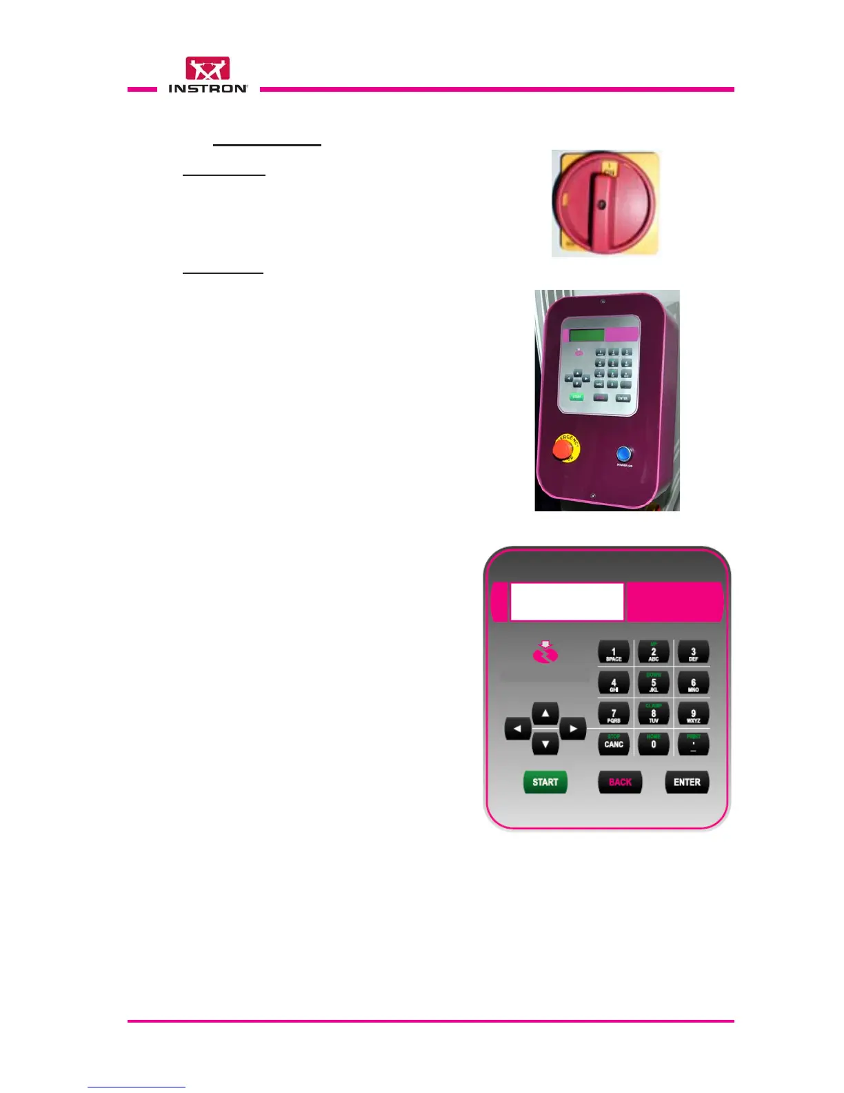
Main Switch
Located underneath of the control box, it
turns ON (I) or OFF (O) the voltage to the
instrument.
O OFF
I ON
Control box
••
••
• Power ON push-button: enable the auxil-
iary circuits of the instrument and switch
on the light inside the button.
••
••
• Emergency-Stop push-button: under
emergency conditions, it allows immedi-
ately to shut off the power to the auxiliary
circuits of instrument.
To restore the controls, rotate the button
about half a turn clockwise, in order to
disengage it from the locked position.
The instrument stays off until the Power
ON push-button is pressed again.
••
••
• "Keypad and Display": the man/machine
interface occurs through the use of the
keyboard and the display. These two com-
ponents are closely connected and they
are used to program the tests, to com-
mand the motorized devices of instru-
ment, to show the results of the test per-
formed and the messages for the opera-
tor in case of problems or errors.
The large liquid crystal display allows up
to 80 characters to be shown on 4 rows.