Page 102 - CEAST 9340 - Instructions for Use and Maintenance 7510.000MN1r ed. 1 rev. 1
8.9.3 SPECIAL HEADS FOR STRIKER
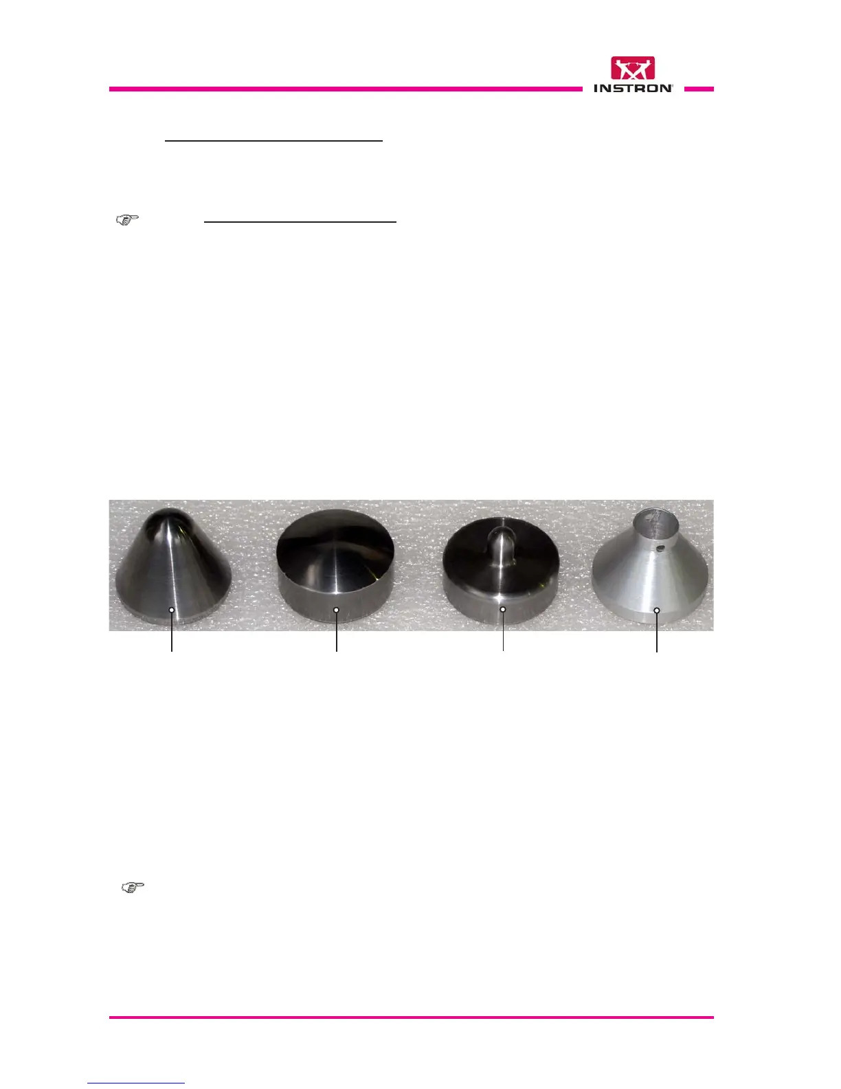
Fig. 4 - Special heads to be installed on striker for impact tests on pipes according to the
ASTM D-2444 Type A, B e C standard.
Interchangeable head
(body diameter 50.8 mm,
tip radius 12.7 mm) code
7529.841 for test on pipes
according to ASTM D-
2444, Type A standard (to
be used together with the
50.8 mm diameter
adapter, code 7529.898)
Adapter (diameter
50.8 mm) code
7529.898 for
interchangeable
heads
Note:- For the heads assembling refer to the Appendix B- Assembly flow chart for
interchangeable head strikers and to the Chapter 8.6.7 Replacement of the
striker’s heads.
PIPE POSITIONING (REF. FIG. 3)
a) Open the door of the chamber.
b) Insert the tube or the fitting in the end of lock bar.
X
X
Note:- Bracket position adjustment: according to the dimensions of tube or fitting to
be tested it is possible to adjust the height of the two brackets so that to maintain
a correct springs tension on the lock bar.
To adjust the brackets height:
- Loosen the lock nut and remove the screw.
- Move the bracket up or down until to find the bracket hole correspondent to
the desired height.
- Tighten the screw and fasten the bracket in position with the lock nut.
c) Lift manually the spring eyelet, insert the lock bar in the bracket slot and engage the
spring eyelet on the end of the lock bar.
X
Interchangeable head
(body diameter 50.8 mm,
tip radius 50.8 mm) code
7529.842 for test on pipes
according to ASTM D-
2444, Type B standard (to
be used together with the
50.8 mm diameter
adapter, code 7529.898)
Interchangeable head
(body diameter 50.8 mm,
tip radius 6.3 mm) code
7529.843 for test on pipes
according to ASTM D-
2444, Type C standard
(to be used together with
the 50.8 mm diameter
adapter, code 7529.898)