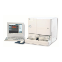
Iris Diagnostics, a Division of Iris International, Inc.
iQ
®
200 Sprint™ (2G) Automated Urine Microscopy Analyzer Service Manual 300-4949 Rev A 01/2005 3
Table of Contents
Cooling Fans # 700-3892 & 700-3412 .............................................................3-18
Fuses and Visible LEDs ...................................................................................3-18
Backplane Fuses and LEDs .............................................................................3-19
PCBA Summary ...............................................................................................3-21
Cardcage..........................................................................................................3-22
High Level Control Board (HLCB), # 101-5000 ................................................3-22
Motor/Scanner Control Board (MSCB), # 101-5001.........................................3-22
DC Valve Board (DCVB), # 101-5043 ..............................................................3-22
Stepper/Scanner/Motor Board (SSMB), # 101-5007........................................3-23
Backplane # 101-5003 .....................................................................................3-23
Signal Interface Concentrators (SICs)..............................................................3-24
Power SIC # 101-5020 .....................................................................................3-24
Pump SIC #101-5020.......................................................................................3-25
FSV SIC # 101-5045 ........................................................................................3-25
SPA SIC # 101-5004 ........................................................................................3-27
SPA SIC Visible LEDs......................................................................................3-27
SPA SIC Push-Button Switches .......................................................................3-27
OBA SIC #101-5053.........................................................................................3-28
Do-All SIC # 101-5046 .....................................................................................3-29
Rear Panel SIC # 101-5030 .............................................................................3-30
STM SIC # 101-5014........................................................................................3-30
Other PCBAs....................................................................................................3-30
ESN Board # 101-5049 ....................................................................................3-30
Lamina ESN # 101-5048 ..................................................................................3-30
FITD PCBA # 101-5041 ...................................................................................3-30
SM Status Board PCBA # 101-5032 ................................................................3-31
STD PCBA # 101-5034 ....................................................................................3-31
Pressure Transducer Board #101-5016 ...........................................................3-31
SPA Optical Board # 101-5052 ........................................................................3-31
LED Visual Indicators .......................................................................................3-31
4 – Adjustments
Accessing the Service Screen............................................................................4-3
Calibration Table ................................................................................................4-4
Calibration Auto-Sets .........................................................................................4-4
Sampler Calibration............................................................................................4-6
Material required ................................................................................................4-6
Procedure...........................................................................................................4-6
Specimen Tube Detector Alignment...................................................................4-7
Material required ................................................................................................4-7
Procedure...........................................................................................................4-7
Specimen Tube Detector Calibration .................................................................4-8
Material required ................................................................................................4-8

 Loading...