Do you have a question about the IRIS iQ 200 Sprint and is the answer not in the manual?
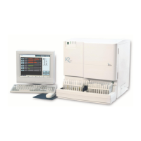
Describes the purpose and configurations of the iQ200 Sprint and 2nd gen Automated Urine Microscopy Analyzer.
Explains navigation, hyperlinks, and bookmark usage within the service manual for efficient access.
Details safety messages, notes, cautions, and biological warnings for safe instrument operation.
Outlines the terms and conditions of the product warranty provided by Iris Diagnostics.
States Iris Diagnostics' liability limitations regarding product sales and usage.
Advises against using non-approved software/hardware to maintain warranty and system reliability.
Provides contact details for Iris Diagnostics, including address, phone, fax, and email.
Details space, workstation, location, and electrical requirements for instrument setup.
Lists the contents of the instrument and starter kit shipping cartons.
Emphasizes safety measures and precautions during the instrument installation process.
Guides on carefully removing the instrument from packaging and connecting the sampler.
Explains how to adjust the analyzer height and sampler feet for proper operation.
Details installing the Lamina container and connecting drain tubing for the instrument.
Outlines connecting video, keyboard, mouse, printer, camera, and serial ports.
Describes jumper configurations on the iQ200 rear panel for Load/Unload ports.
Provides step-by-step instructions for installing the iQ200/AX-4280 bridge connection kit.
Details connecting the Load Station to the iQ200 sampler or AX-4280.
Guides on assembling and connecting the Unload Station to the iQ200 sampler.
Outlines powering on, initializing the system, and performing test runs like focus and calibration.
Describes running focus, calibration, control racks, and verifying connections.
Directs to Operator's Manual for setup procedures before starting operation.
Explains the parts and function of the STM, including the Sampler and Specimen Tube Detector.
Describes the function of the Rinse and Waste Well in sample processing and drainage.
Details the Air, Waste, Rinse, and Fill diaphragm pumps and their functions.
Explains the Cannula, Lamina, and Evacuation peristaltic pumps and their roles.
Describes switches for pump cover closure and cassette presence detection.
Details the Lamina Tank, its liquid level sensors, and their functions.
Explains the Air Tank's function in maintaining air pressure for specimen mixing.
Lists and describes the Drain, Evacuation Bypass, Lamina Bypass, Cannula Bypass, and Pipettor Bypass valves.
Describes the Air Mix and Air Charge valves and their functions.
Details the OBA, its components (Flow Cell, Strobe, Camera, Objective), and function.
Explains the power supply assembly, cooling fans, and visible LEDs indicating status.
Details fuse ratings, backplane fuses, and visible LEDs indicating status and faults.
Describes the cardcage, backplane, and key control boards like HLCB, MSCB, DCVB.
Details SSMB boards, backplane connectors, and Signal Interface Concentrators (SICs).
Details various SICs (Power, Pump, FSV, SPA, OBA, Do-All) and other PCBAs.
Describes Pressure Transducer, SPA Optical Boards, and LED Visual Indicators.
Guides on launching and switching to the service application for calibration and adjustments.
Explains the calibration table entries and the use of calibration auto-sets.
Details the procedure for calibrating the sampler's #5 test tube position.
Describes calibrating the distance for rack ejection to the unload station.
Guides on setting the alignment and sensitivity of the specimen tube detector.
Details the procedure for calibrating the air pressure system for optimal performance.
Provides steps for connecting, loading the tool, and performing barcode reader alignment.
Explains collimation and guides on condenser alignment using the video view.
Covers flow cell removal, installation, lateral, and tilt adjustments.
Guides on launching and switching to the service application from the main screen.
Explains the process of establishing a link with the analyzer control system.
Describes live operation, the Tree View Pane, and the Fluid Schematic Pane.
Explains using commands, preset moves, and monitoring sensor values.
Explains calibration table entries, auto-sets, and instrument sequences.
Explains the representation of pumps and valves in the fluid schematic.
Guides on using menus and understanding the status bar information.
Describes using the Jog menu for precise motor positioning and calibration.
Explains link status indicators and troubleshooting steps for connection failures.
Lists sequences and sensor IDs for troubleshooting master controller and SPA issues.
Addresses common questions about sensor values and component controller assignments.
Explains navigating the service tree structure and accessing system versions.
Guides on rebooting and logging in to bypass instrument error conditions.
Explains how to translate hexadecimal valve failure codes in error reports.
Provides common error scenarios and initial troubleshooting steps for system issues.
Addresses issues like "iQ 200 fails to go to Standby" and "ID errors/Mismatch".
Covers sequential flag errors, image acquisition errors, and valve failures.
Details errors related to sample processing time, controls, and system standby.
Troubleshoots issues with fluid flow, cell counts, and fluid system bubbles.
Explains how to interpret event log error messages for SPA, FBA, and OBA failures.
Lists the electronic and software functions of the Microscopy Module.
Provides an overview of the instrument's internal cabling and connections.
Illustrates the backplane layout within the cardcage and board placement.
Shows rear view of backplane, fuses, and connections to internal module parts.
Summarizes component addresses, board types, and their interface assignments.
Details hardware bit assignments and parameters for various components.
Provides a cross-reference for hardware assignments of motors, pumps, and sensors.
Lists Electronic Serial Number (ESN) I2C addresses for system components.
Presents a block diagram of the SMCS assemblies for the iQ200 system.
Shows the schematic of the 700-3800 System Fluid Assembly.
Details the state records for the Master Controller, including index, states, and parameters.
Lists the state records for the SPA module, including states, parameters, and descriptions.
Details the state records for the FBA module, including states, parameters, and descriptions.
Lists the state records for the STM module, including states, parameters, and descriptions.
Outlines semi-annual and annual preventive maintenance procedures for the iQ200.
Lists the required kits for performing preventive maintenance and certification.
Guides on cleaning external surfaces and flushing the fluidic system.
Details the procedure for cleaning the Rinse/Waste Well assembly.
Explains replacing cassettes for Cannula, Evacuation, and Lamina pumps.
Guides on replacing various tubing assemblies and the specimen filter.
Refers to Chapter 4 for alignment procedures like sampler, tube detector, and scanner verification.
Covers SPA alignment verification and fluidic system inspection for leaks.
Guides on verifying optic positions, flow cell tilt, collimation, and lateral adjustments.
Details performing Auto-Focus, calibration, and control runs for performance verification.
Instructs on reporting maintenance results using the PM checklist form.
| Brand | IRIS |
|---|---|
| Model | iQ 200 Sprint |
| Category | Laboratory Equipment |
| Language | English |