3. Align the boom holes in the mounng brackets with the holes on the side panels of the switch
chassis.
4. Insert mounng screws into the aligned holes. Tighten the screws by using the
Phillips (+) screwdriver.
5. Ensure that the other holes in the mounng brackets are aligned with the holes in the side panels.
Insert a screw in each hole and ghten the screws by using the Phillips (+) screwdriver.
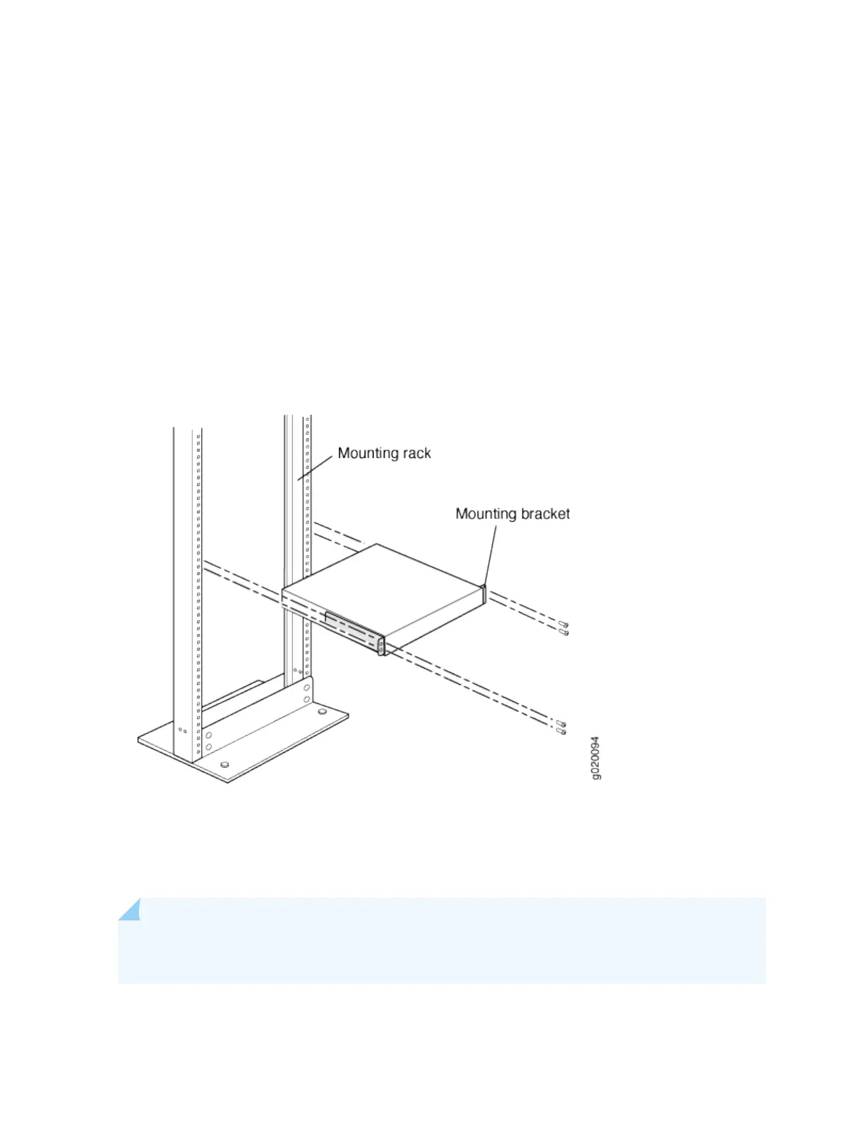
6. Have one person grasp both sides of the switch, li the switch, and posion it in the rack, aligning
the mounng bracket holes with the threaded holes in the rack or cabinet rail. Align the boom hole
in both the mounng brackets with a hole in each rack rail, making sure the chassis is level. See
Figure 57 on page 175.
Figure 57: Mounng the Switch on Two Posts of a Rack
7. Have a second person secure the switch to the rack by using the appropriate screws. Tighten the
screws.
8. Ensure that the switch chassis is level by verifying that all screws on one side of the rack are aligned
with the screws on the other side.
NOTE: We recommend that you install cover panels in the unused uplink module and power
supply slots.
175
 Loading...


