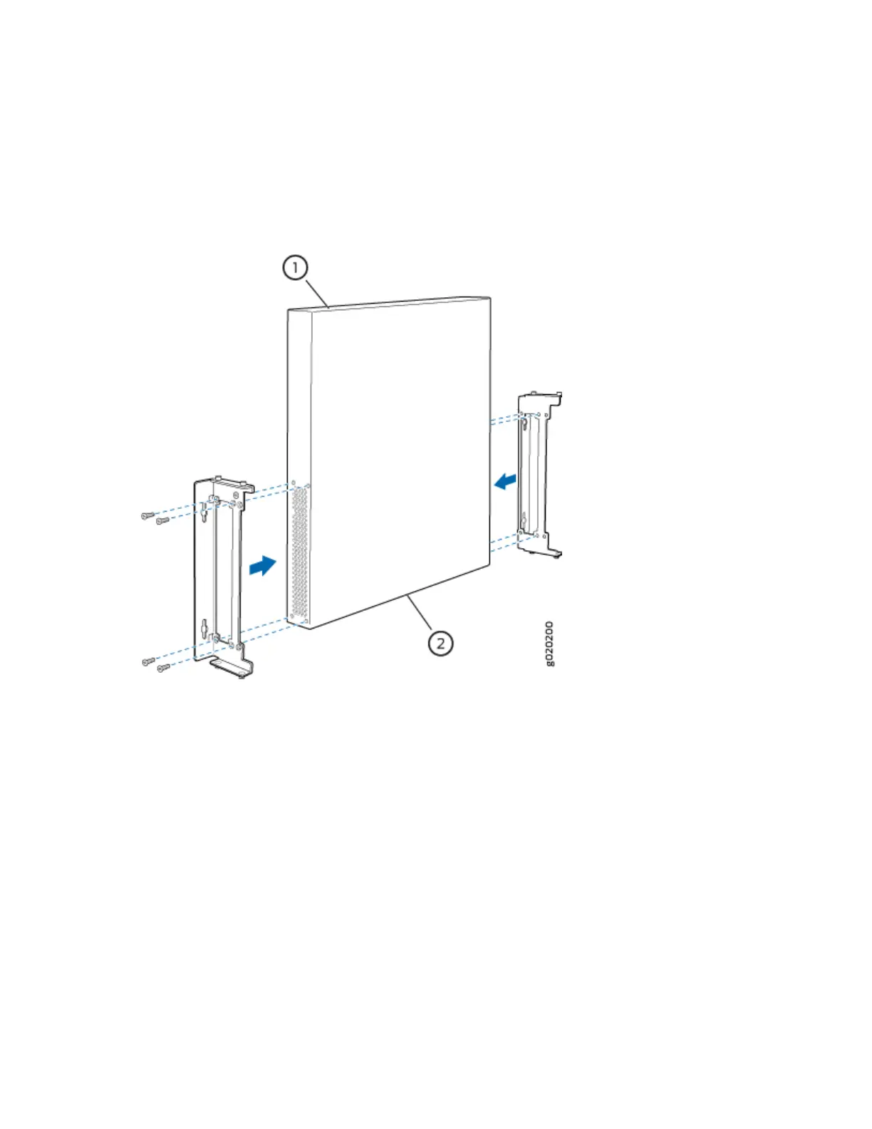
1. Aach the wall-mount brackets to the sides of the chassis by using four of the wall-mount bracket
screws on each side (see the representaon in Figure 61 on page 182). Use the screwdriver to
ghten the screws.
Figure 61: Aaching Wall-Mount Brackets to the Switch Chassis
2.
If you are mounng two switches together, line the second switch on top of the rst and aach it to
the mounng brackets by using two wall-mount bracket screws on each side (see the representaon
in Figure 62 on page 183).
3. Insert the mounng screws in the wall. If you are mounng EX4300 switches except EX4300-48MP
and EX4300-48MP-S switches, insert the top pair of mounng screws 474.35 mm apart, and insert
the second pair of mounng screws 151.81 mm directly below the rst set. If you are mounng
EX4300-48MP and EX4300-48MP-S switches, insert the top pair of mounng screws 474.2 mm
apart, and insert the second pair of mounng screws 152 mm directly below the rst set (see Figure
63 on page 184 and Figure 64 on page 185).
If the mounng screws are inserted in a wall board with no stud behind it, you must use dry wall
anchors rated to support 75 lb (34 kg). Insert the screws into wall studs wherever possible to provide
added support for the chassis.
Drive the screws only part way in, leaving about 1/4 in. (6 mm) distance between the head of the
screw and the wall. Use the screwdriver to drive the screws in.
182