1. Aach the grounding strap to your bare wrist and to a site ESD point.
NOTE: The power supply slots are at the right end of the rear panel on 24-port and 48-port
switches, and at the le end on 32-port switches.Figure 67 on page 198 shows how to
connect an AC power cord to an AC power supply installed on 24-port or 48-port EX4300
switches. The procedure is the same for 32-port EX4300 switches.
2. Ensure that the power supplies are fully inserted in the chassis and the latches are secure. If only
one power supply is installed, ensure that a cover panel is installed over the second power supply
slot.
3. Locate the power cord and power cord retainer shipped with the switch; the cords have plugs
appropriate for your geographical locaon. See "AC Power Cord Specicaons for an EX4300
Switch" on page 105.
4. Push the end of the retainer strip into the hole next to the inlet on the power supply face plate unl
it snaps into place. Ensure that the loop in the retainer strip faces toward the power cord.
5. Press the small tab on the retainer strip to loosen the loop. Slide the loop unl you have enough
space to insert the power cord coupler into the inlet.
6. Insert the power cord coupler rmly into the inlet.
7. Slide the loop toward the power supply unl it is snug against the base of the coupler.
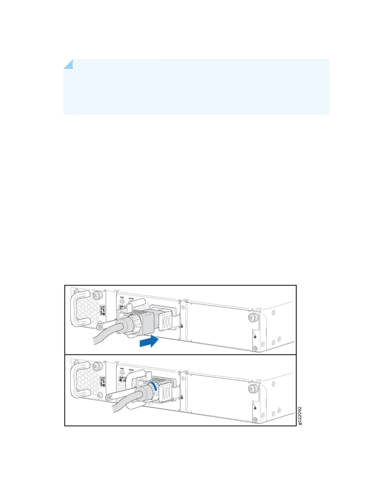
8. Press the tab on the loop and draw out the loop into a ght circle (see Figure 67 on page 198).
Figure 67: Connecng an AC Power Cord to an AC Power Supply in an EX4300 Switch
198
 Loading...


