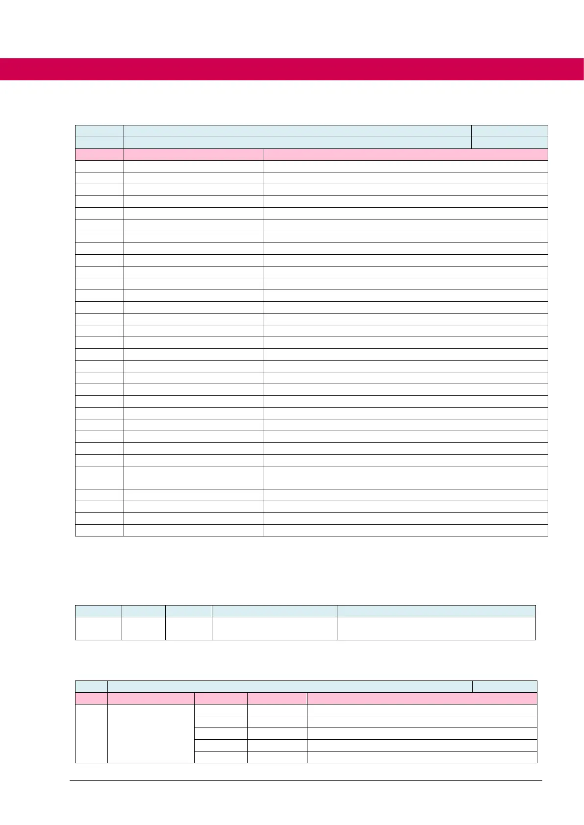
Contouring error according CIA402 standard
Short-term overload level [in %]
Long-term effective inverter load [in %]
motor prot counter (ru32)
Motor protection counter [in %]
positive torque limit (ru50)
resulting positive torque limit
negative torque limit (ru51)
resulting negative torque limit
Long-term load of the motor [in %]
Switching frequency [in kHz]
Motor current [in % short-time current limit]
Analog input 1 before input level [in %]
AN1 after gain display (ru43)
Analog input 1 after input level [in %]
Analog input 2 before input level [in %]
AN2 after gain display (ru45)
Analog input 2 after input level [in %]
analog REF display (ru48)
Value of the REF signal [in %]
analog AUX display (ru49)
Value of the AUX signal [in %]
Run to the homing point is done
Ramp output value (internal) – ru08 [in rpm]
smoothed ramp output value (internal) – ru08 [in rpm]
brake control state (st04)
Status of the brake control
PWM signal for valve control of a liquid cooler
filtered actual speed (ru08 after is39 time) [in rpm]
blockade status (pn87[6])
Status of the blockade handling
motor cooling PWM out state
PWM signal for valve control of a liquid cooler
Setpoint speed [in rpm] after ramp/spline, PT1 element and po-
sition controller handle (input variable of the speed controller)
7.2.9.3 Operators
The operator to be used is selected in do03 flag operator mode. Additionally the sign of
the operands can be influenced.
Operator (comparison operation >, <, =,
etc.)
The bits in do03flag operator mode have the following meanings:
A AND B / TRUE, , if min 1 bit is set
A OR B / TRUE, if min 1 bit is set

 Loading...


