118 Keysight EXG and MXG X-Series Signal Generators User’s Guide
Optimizing Performance for All Models
Using External Leveling (N5173B/83B Only)
4. Determine the output amplitude range, see “Determining the Signal Generator’s Amplitude
Range” on page 119
5. Set the displayed power value, see “Adjusting the Signal Generator Display’s Amplitude
Value” on page 120
Equipment Setup
Set up the equipment as shown in Figure 5-22 on page 118. Place the external detector (detector
and coupler/power splitter) as close as possible to the DUT.
Recommended Equipment
— Keysight 8474E negative detector
— Keysight 87301D directional coupler
— cables and adapters, as required
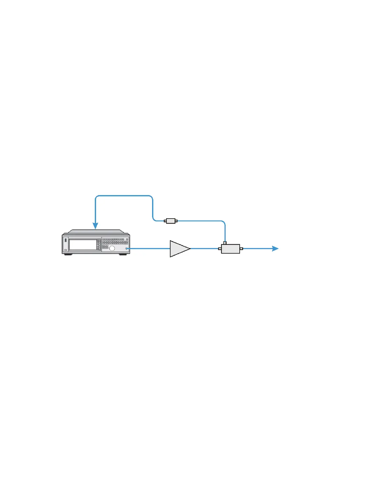
Figure 5-22 Typical External Leveling Setup using a Directional Coupler
Configuring the Carrier
1. Press Preset.
2. Set the carrier frequency.
3. Set the power level to 0 dBm:
— If the signal generator has Options 1E1 and 520, set the output attenuator to zero dBm:
a. Press AMPTD > Atten/ALC Control > Atten Hold Off On to On.
b. Press Set Atten > 0 > dB.
c. Press Set ALC Level > 0 > dBm.
Selecting External Leveling
Press AMPTD > Leveling Control > Leveling Mode > Pwr Meter Cont.
Leveled Signal
Signal Generator
Coupler
Amplifier
Negative Detector
RF OUTPUT
ALC INPUT